Contact element with crimp section

a technology of contact element and crimp section, which is applied in the direction of permanent deformation connection, coupling device connection, electrical apparatus, etc., can solve the problems of increasing the risk of wire breaking, and closing of small depressions on the side walls of the crimp section

Inactive Publication Date: 2000-05-02
ROBERT BOSCH GMBH
View PDF4 Cites 78 Cited by
  • Summary
  • Abstract
  • Description
  • Claims
  • Application Information

AI Technical Summary

Problems solved by technology

Thus, after crimping, the wire has a smaller diameter in the area of the annular channels and the risk of the wire being broken increases, which is obviously undesirable.
This, however, has the undesirable result that the small depressions on the side walls of the crimp section are closed due to the deformation of the side walls before the wires can be pressed into the depressions.
Thus also in this case annular channels are formed on the wire, resulting in the aforementioned weakening of the wire and an increase in the risk of wire breakage.

Method used


Image

  • Contact element with crimp section
  • Contact element with crimp section
  • Contact element with crimp section

Examples


Embodiment Construction

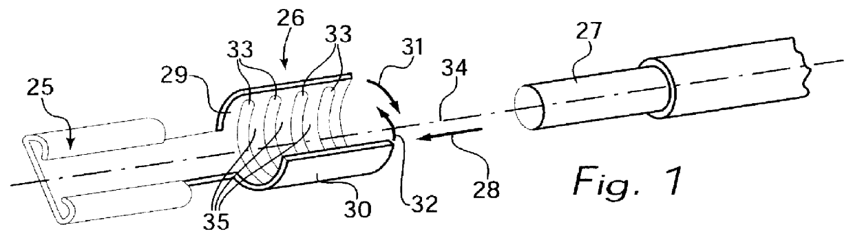
FIG. 1 shows a conventional contact element prior to crimping with a conductor 27. At one end, the contact element has a plug-and-socket connector part 25, which can be pushed onto a flat contact plate to wire a machine or a part of a system. At the other end of the contact element, a crimp section 26 is provided, which has depressions in the form of grooves 33 extending perpendicularly to the longitudinal axis 34 of the conductor on its inner surface. Conductor 27 can be a single, solid wire or a braided cable and is pushed in the direction of arrow 28 into crimp section 26. Then crimping is performed, during which side walls 29, 30 of crimp section 26 are bent in the direction of arrows 31, 32. Conductor 27 is also deformed during crimping, being primarily pressed into grooves 33 and displaced by webs 35 between grooves 33. Webs 35 form annular grooves 36 on the conductor surface and thus reduce the conductor cross section in this area. FIG. 2 clearly shows annular grooves 36, pro...


PUM


Abstract

PCT No. PCT/DE96/01684 Sec. 371 Date Jun. 24, 1998 Sec. 102(e) Date Jun. 24, 1998 PCT Filed Sep. 9, 1996 PCT Pub. No. WO97/16867 PCT Pub. Date May 9, 1997To reduce the risk of breakage and yet ensure good electric and thermal conductivity, pull-off strength and long service life of the connection, when connecting a contact element to a conductor (1) by crimping, the inner surface of the crimp section (6), in contact with the conductor (1), is provided with deformations that are grooves (2) and ribs running crosswise and obliquely to the longitudinal axis of the conductor (1).

Description

The present invention relates to a contact element with a crimp section for conductors, with deformations on the inner surface of the crimp section provided for contact with the conductor.BACKGROUND INFORMATIONElectric wires and cables with such contact elements, which exist in numerous forms as cable lugs, receptacles, or clamps, are used in different apparatuses and systems. Such contact elements allow a reliable and detachable electric connection to be quickly established. The advantage of crimp connections is that wires can be connected to the contact element using machines, resulting in a sufficiently stable, conductive connection between wire and contact element.Efforts have continued to be made, however, to improve the connection between the electric conductor and the contact element concerning its electric and thermal conductivity, pull-off strength, service life, and resistance to corrosion so that it can withstand the effects of impacts, temperature fluctuations, moisture,...

Claims


Application Information

Patent Timeline
Patent Type & Authority Patents(United States)
IPC IPC(8): H01R4/10H01R4/18H01R13/115
CPCH01R4/188H01R13/115H01R4/18
Inventor NGUYEN, NGOC-THACHBAUCH, HELMUTMEYER, GUNTER
Owner ROBERT BOSCH GMBH
Why Eureka
Try Eureka