Air bag for protecting passenger from side collision which has uniform inflation characteristics

a technology of air bags and inflation characteristics, applied in the field of air bags, can solve the problem that the inner pressure cannot be guaranteed on the lower side of the air bag, and achieve the effect of ensuring the safety of passengers and passengers

Inactive Publication Date: 2000-05-16
TOYODA GOSEI CO LTD
View PDF8 Cites 66 Cited by
  • Summary
  • Abstract
  • Description
  • Claims
  • Application Information

AI Technical Summary

Problems solved by technology

Further, when the chest area or vicinity head area of a passenger is to be protected, the side collision air bag is incorporated in a portion of a door panel or a seat rear the passenger's head in a folded state because door glass or the like is arranged rear of the head of the passenger an

Method used


Image

  • Air bag for protecting passenger from side collision which has uniform inflation characteristics
  • Air bag for protecting passenger from side collision which has uniform inflation characteristics
  • Air bag for protecting passenger from side collision which has uniform inflation characteristics

Examples


first embodiment

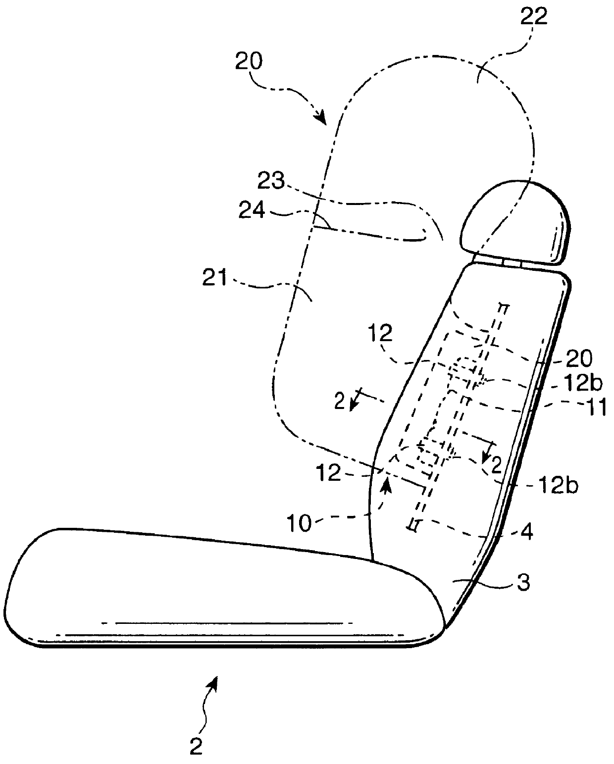
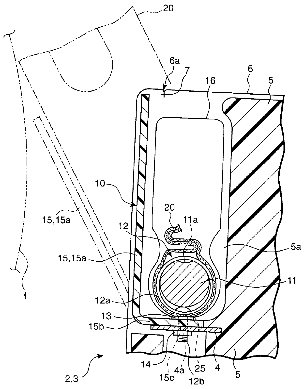
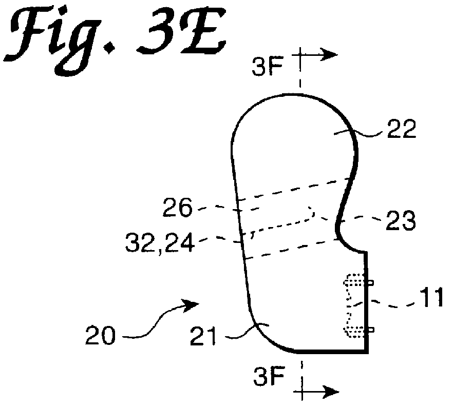
Further, according to the air bag 20 of the first embodiment, when the chest of a passenger interferes with the lower chamber 21 in the midst of expanding the air bag prior to completion of the expansion, the flow of the expansion gas is regulated by the gas flow port 23 provided between the lower chamber 21 and the upper chamber 22. Therefore, even when the expansion gas is going to escape into the upper chamber 22, the flow of the expansion gas is regulated by the gas flow port 23 and the inner pressure of the lower chamber 21 of the air bag 20 is prevented from falling.

That is, even if a passenger interferes with the lower chamber 21 of the air bag 20 in lie midst of expansion, sufficient inner pressure can be ensured in the lower chamber 21 of the air bag 20. Accordingly, the output of the inflator 11 for supplying the expansion gas can be decreased.

Therefore, not only is the air bag arranged substantially in the vertical direction when the air bag is expanded, but even when the...

fifth embodiment

Furthermore, an air bag 70 shown in FIGS. 8A-8D may be constituted. The air bag 70 is constituted by the lower chamber 21 on the lower side and the upper chamber 22 on the upper side in the expanded state. The lower chamber 21 and the upper chamber 22 are partitioned by the weir 24 at which the gas flow port 23 is arranged on the side of the rear portion of the vehicle. An emergency communication port 73 capable of connecting the lower chamber 21 and the upper chamber 22 is provided on the side of the front portion of the vehicle in the weir 24. According to the air bag 70, the emergency communication port 73 is opened only when the inner pressure of the lower chamber 21 is increased to more than the normal inner pressure value.

The air bag 70 is also provided with a fragile portion 24b for closing the communication port 73 on the side of the front portion of the vehicle of the weir 24 as in the air bag 60. Due to the fragile portion 24b, the bonding strength between the opposed bas...


PUM


Abstract

An air bag for side collision is arranged substantially in the vertical direction between a vehicular inner wall and a passenger in an expanded state of the air bag. A lower side of the air bag is folded to be incorporated into the lower side in the expanded state. The lower side of the air bag in the expanded state is the upstream side of flow of expansion gas. The air bag has a narrowed gas flow port for regulating the flow of the expansion gas between the lower side and the upper side of the air bag in the expanded state so that the lower side can ensure sufficient inner pressure even when the passenger interferes with expansion of the lower side of the air bag during expansion, since the flow of the expansion gas is regulated by the gas communication port provided between the lower side and the upper side of the air bag. As a result, an inflator having small output can be used.

Description

This application is related to and claims priority under 35 U.S.C. .sctn.119 from Japanese Patent Application Nos. Hei 9-043854 and 9-180914, incorporated herein by reference.1. Field of the InventionThe present invention relates to an air bag in a vehicle for protecting a passenger from a side collision. This air bag is arranged substantially in the vertical direction between a vehicular inner wall of an automobile and a passenger when the air bag is expanded.2. Description of Related ArtConventionally, an air bag for protecting a passenger from a side collision (hereinafter, abbreviated as side collision air bag or air bag) has been incorporated in a door panel or a seat in a folded state. The side collision air bag has been arranged between a vehicular inner wall of an automobile and a passenger when the air bag is expanded (refer to Japanese Unexamined Patent Publication Number JP-A-7-117610 and Japanese Unexamined Patent Publication Number JP-A-8-156668).Further, when the chest...

Claims


Application Information

Patent Timeline
IPC IPC(8): B60R21/16B60R21/20B60R21/207B60R21/231B60R21/233B60R21/2342B60R21/237
CPCB60R21/23138B60R2021/23316B60R21/237B60R21/2342
Inventor ASANO, MASAKAZUSAKAMOTO, NOBUHIKOKOBAYASHI, HIROYUKI
Owner TOYODA GOSEI CO LTD
Why Eureka
Try Eureka