Cooler for fitting to the rear or side wall or the door of a switching cabinet

Inactive Publication Date: 2000-05-23
RITTALWERK RUDOLF LOH GMBH & CO KG
View PDF5 Cites 49 Cited by
  • Summary
  • Abstract
  • Description
  • Claims
  • Application Information

AI Technical Summary

Problems solved by technology

Such cooling devices are only laid out as heat exchangers and the separation between the interior air circulation cycle and the exterior air circulation cycle always presents difficulties.
If this separation is not complete, the entry of moistu

Method used


Image

  • Cooler for fitting to the rear or side wall or the door of a switching cabinet
  • Cooler for fitting to the rear or side wall or the door of a switching cabinet

Examples


Embodiment Construction

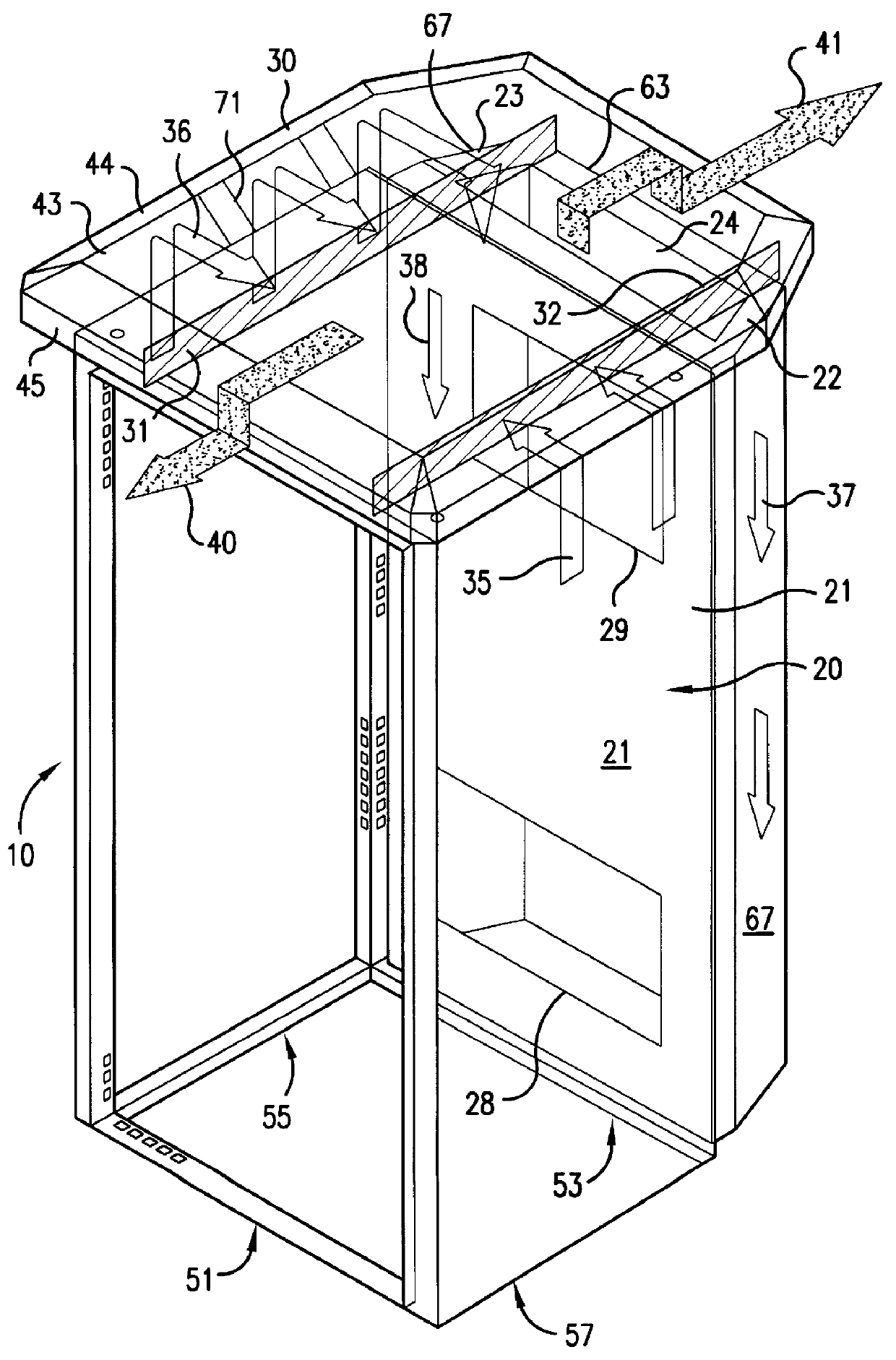
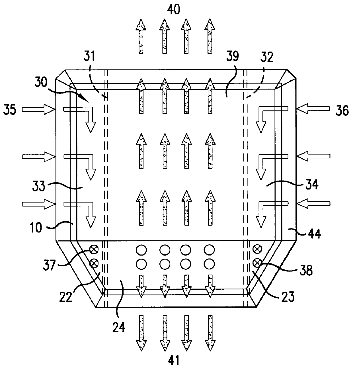
Only the frame of the switchgear cabinet 10 is shown in FIG. 1. The frame 10 defines a polyhedron having framing members for at least a front wall 51, a rear wall 53, and at least two lateral walls 55, 57. The rear of the frame is closed off by a cooling device, of which only the cooling device housing 20 is shown in the drawings, since the design of the cooling device is of no importance for this invention. The cooling device housing defines a polyhedron having at least a front wall 21, a rear wall 63, and at least two lateral walls 65, 67. The cooling device housing, which is trapezoidal in cross section, closes off the back of the frame flush on all sides by means of the front wall 21. However, the cooling device can also replace a lateral wall of the switchgear cabinet 10, or can itself be designed as a door. The cooling device is in communication with the interior of the switchgear cabinet via an inlet opening 28 and outlet opening 29. The cooling device housing 20 is divided i...


PUM


Abstract

PCT No. PCT/EP97/00657 Sec. 371 Date Sep. 14, 1998 Sec. 102(e) Date Sep. 14, 1998 PCT Filed Feb. 13, 1997 PCT Pub. No. WO97/34454 PCT Pub. Date Sep. 18, 1997A cooler which can be fitted on a rear wall or a side wall or a door of a switching cabinet and can be connected thereto via an intake and an inlet aperture of an internal circuit. According to the invention, rain and dustproofing is improved because alongside a central ventilation shaft open at the top, the cooler housing has vertical ventilation chambers open at the top as part of an external circuit hermetically separated from the internal circuit, the top of the switching cabinet and cooler housing is covered by a roofing component spaced therefrom which projects on all sides beyond the control box and the cooler housing and leaves a peripheral ventilation slot opening downwards. The roofing component is divided by two partitions into three chambers which communicate with the ventilation shaft and both ventilation chambers in the cooler housing.

Description

1. Field of the InventionThis invention relates to a cooling device, which can be installed in place of a rear wall, lateral wall or door of a switchgear cabinet and which can be brought in connection with the rear wall, the lateral wall or the door via an inlet opening and an outlet opening of an interior cycle.2. Description of Prior ArtSuch cooling devices are only laid out as heat exchangers and the separation between the interior air circulation cycle and the exterior air circulation cycle always presents difficulties. If this separation is not complete, the entry of moisture into the switchgear cabinet cannot always be unambiguously prevented. These difficulties increase considerably if the switchgear cabinet with the cooling device is placed in the open, since protection against rain and dirt particles is added.It is one object of this invention to considerably improve protection of the heat exchanger of a cooling device of the type mentioned against condensation water, rain ...

Claims


Application Information

Patent Timeline
IPC IPC(8): H02B1/00H02B1/56H05K7/20
CPCH02B1/56H05K7/206H02B1/565H05K7/20
Inventor DIEBEL, MICHAELEDELMANN, ACHIMNICOLAI, WALTERSTRACKBEIN, HEINRICH
Owner RITTALWERK RUDOLF LOH GMBH & CO KG
Why Eureka
Try Eureka