Coupling device for tube

a technology of coupling device and tube, which is applied in the direction of coupling, bends, manufacturing tools, etc., can solve the problems of affecting the homogeneous heating of each and every tube of the assembly, the bulk size of the assembly, and the complexity of the overall configuration

Inactive Publication Date: 2000-06-06
LUO CHUNG I
View PDF7 Cites 29 Cited by
  • Summary
  • Abstract
  • Description
  • Claims
  • Application Information

AI Technical Summary

Problems solved by technology

However, the assembly has a bulk size after the tubes are connected with each other.
Furthermore, the overall configuration becomes also complicate.
It will be difficult to get a homogeneous heating to each and every tube of the assembly.
Both the heating and cooling of the assembly can not be simultaneously reached.
In light of this, the heat treatment becomes more and more difficult.
Not only will increase the cost of the heat treatment, but will also be difficult to get a homogeneous heat treatment effect.
The cost increase tremendously as the overall structure becomes complicate.
No doubt the overall cost will be increased.
While the bulk size of the assembly increases, the heating chamber becomes larger and larger.
This will also lower the throughput of the heating chamber as a limited number of assemblies can be heated and cooled within the heating chamber.
The manufacturing cost will be increased as well.
There is another problem encountered by the prior art.
Those two deformations will negatively influence the aesthetic appearance and outer dimension of assembly or work.

Method used


Image

  • Coupling device for tube
  • Coupling device for tube
  • Coupling device for tube

Examples


Embodiment Construction

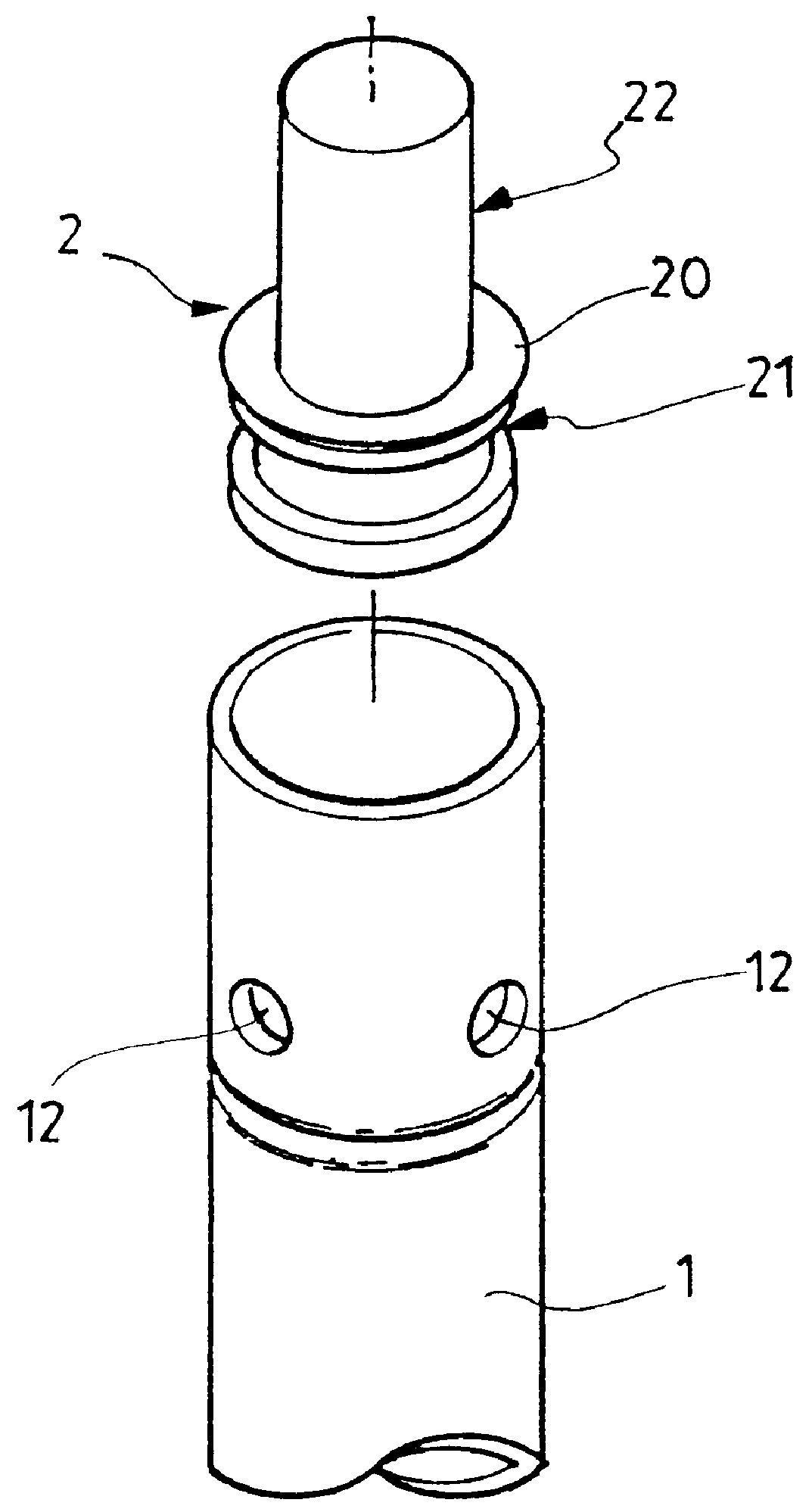
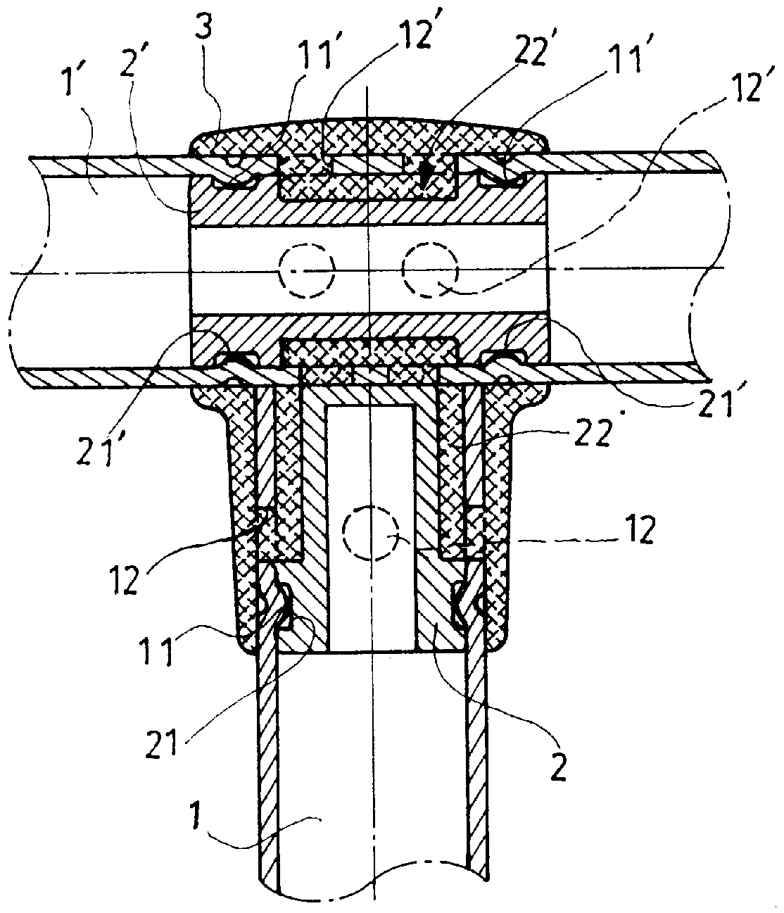
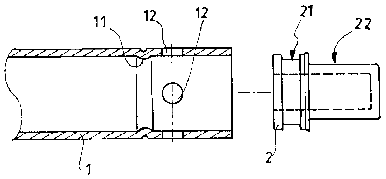
Referring to FIGS. 1 and 2, the coupling device includes an insert 2 that can be positioned within the tube 1. The insert 2 includes an enlarged portion 20 that has annular groove 21 thereof, and a receiving space 22. The tube 1 is provided with a plurality of through holes 12 in the middle portion or end portions. The insert 2 can be positioned within the tube 1. The outer wall of the tube 1 is further machined to form an annular recess 11 that is corresponding to the annular groove 21 of the insert 2. By this arrangement, the insert 2 can be positioned within the tube 1 by the interference fit between the annular recess 11 and the annular groove 21.

When the first tubes 1 and second tube 1' are provided with inserts 2, 2' and are arranged in T-shape arrangement, then an enclosing element 3 can be coated to the joint area to connect the first tube 1 and the second tube 1'.

By this arrangement, the insert 2 can be firstly positioned within the tube 1. Then the outer wall of the tube 1...


PUM

PropertyMeasurementUnit
areaaaaaaaaaaa
rigidityaaaaaaaaaa
strengthaaaaaaaaaa

Abstract

The present invention relates to an improved coupling device for tube and that is configured with a tube and an insert that can be fixedly disposed within the tube. The insert includes at least an enlarged portion that has an annular groove thereof, and a receiving space. The tube is provided with a plurality of through holes at the middle portion or end portions. The insert can be disposed within the tube and the outer of the tube is machined to form an annular recess corresponding to the annular groove in a manner such that the insert is fixedly disposed within the tube. Wherein each of the two tubes is provided with an insert in the position to be connected, and the tubes is arranged side-by-side at the area to be connected. An enclosing element is deployed to the connecting area such that the tubes are fixedly connected.

Description

The present invention relates to a coupling device, more particularly, to a coupling device for tubes to be assembled with each other. The tubes can be undergone a heat treatment prior they are connected. The deformation during the welding can be therefore eliminated.DESCRIPTION OF PRIOR ARTAs shown in FIGS. 8 and 9, in connecting two tubes that are arranged in T-shape arrangement, the first tube (a) shall be cut with a cutout (a1) in the area to be connected. Then the cutout (a1) of the first tube (a) is rested onto the second tube (b). Then a welding process will be performed along the joint between the outer wall of the second tube (b) and the cutout (a1) of the first tube (a).As shown in FIG. 10, the first and second tubes (a, b) are connected in X-shape arrangement. In this case, even no need of cut a cutout on both the first and second tubes (a, b), the rigidity and strength on the welding area will be weakened. In order to ensure the rigidity and strength of the overall struc...

Claims


Application Information

Patent Timeline
Patent Type & Authority Patents(United States)
IPC IPC(8): F16L37/00F16L37/08F16L41/02
CPCF16L37/08F16L41/021Y10T403/473Y10T403/4941Y10S285/906
Inventor LUO, CHUNG-I
Owner LUO CHUNG I
Why Eureka
Try Eureka