Suture welding device

a welding device and suture technology, applied in wound clamps, medical science, surgery, etc., can solve the problems of quite a bit of manual dexterity and experience, and the final process of tying a knot in the stitching is very difficul

Inactive Publication Date: 2000-06-20
MICROLINE SURGICAL INC
View PDF7 Cites 437 Cited by
  • Summary
  • Abstract
  • Description
  • Claims
  • Application Information

AI Technical Summary

Problems solved by technology

Stitching a surgical or traumatic wound closed within an endoscopic work space requires quite a bit of manual dexterity and experience, and the final process of tying a knot in the stitching is very difficult.

Method used


Image

  • Suture welding device
  • Suture welding device
  • Suture welding device

Examples


Embodiment Construction

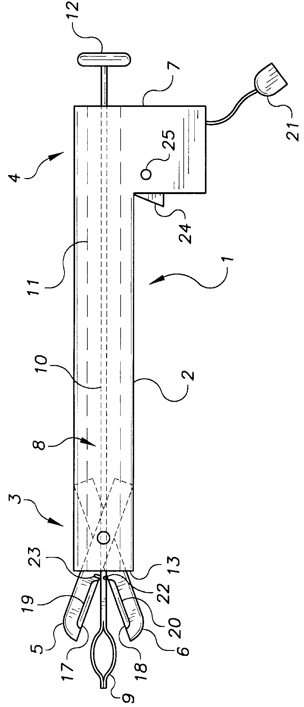
FIG. 1 illustrates a suture welding device 1. The welding device is comprised of a long insertion rod 2, with a distal end 3 and a proximal end 4. The distal end carries a pair of grasping jaws 5 and 6 mounted pivotably within the distal end and protruding from the distal end of the insertion rod. The proximal end is fitted with a handle assembly 7. A snare 8 including a snaring portion 9 mounted on the distal end of a snare rod 10 is slidably and rotatably disposed within the lumen 11 in the d insertion rod 2. The snare also includes the handle 12 mounted on its proximal end. The snare exits out the distal end of the insertion rod, and as illustrated exits through a port in the distal face 13 of the insertion rod. The snare provides a means for initially grasping loose suture ends and drawing the suture ends into close proximity to the jaws. The jaws provide a second means for grasping the suture ends after they have been picked up by the snare.

The insertion rod may be any convenie...


PUM


Abstract

Devices for welding suture segments in lieu of tying knots in sutures applied during endoscopic surgery. The devices provide for snaring loose suture ends and drawing the suture ends into a space between heating surfaces, and provide for closing the heating surfaces

Description

The devices described below relate to the field of surgical devices and methods, specifically to the field of endoscopic suturing techniques.BACKGROUND OF THE INVENTIONSSutures and stitching are well known techniques for repairing body tissue after injury or surgery. Many types of surgery, such as gall bladder removal, hernia repair, and even coronary bypass surgery can now be performed through the techniques of endoscopic surgery. Endoscopic surgery, also referred to as laparoscopic surgery, minimally invasive surgery, or bloodless surgery, is performed through small incisions in the body with long slender cutting and grasping devices which can be inserted into the body through the small incisions. The devices have small working mechanisms on the distal end (the end of the instrument that is inserted into the body) and convenient handles and operating mechanisms (for controlling the working mechanisms on the proximal end). Surgeons use endoscopic scalpels and scissors for cutting t...

Claims


Application Information

Patent Timeline
Patent Type & Authority Patents(United States)
IPC IPC(8): A61B17/04A61B17/00A61B17/06
CPCA61B17/04A61B2017/0619A61B2017/00504A61B17/0485
Inventor MOLLENAUER, KENNETH H.KUCKLICK, THEODORE
Owner MICROLINE SURGICAL INC
Why Eureka
Try Eureka