Flat knitting machine with movable loop forming plates

a knitting machine and forming plate technology, which is applied in the field of flat knitting machines with movable loop forming plates, can solve the problems of low fabric market value, irregular spacing between wales in full knitting, and the sinker loop of the knitted structure that is knitted by using both the front and back needle beds is larger relative to the sinker loop of the knitted structur

Inactive Publication Date: 2000-06-27
SHIMA SEIKI MFG LTD
View PDF7 Cites 26 Cited by
  • Summary
  • Abstract
  • Description
  • Claims
  • Application Information

AI Technical Summary

Problems solved by technology

Hence the sinker loop is expanded relative to the needle loop in the knitted fabric, and this lowers the market value of the fabric.
As a result, it poses a problem of irregular spacing between wales in full knitting.
In the case of a flat knitting machine having conventional fixed sinkers or movable sinkers, when a knitted structure that is knitted by using only one needle bed, such as plain stitch structure, and a knitted structure that is knitted by using needles of both front and back needle beds, such as rib stitch structure, are mixed in the same course, it poses a problem that the sinker loop of the knitted structure that is knitted by using both the front and back needle beds is larger relative to the sinker loop of the knitted structure that is knitted by using only one needle bed.

Method used


Image

  • Flat knitting machine with movable loop forming plates
  • Flat knitting machine with movable loop forming plates
  • Flat knitting machine with movable loop forming plates

Examples


first embodiment

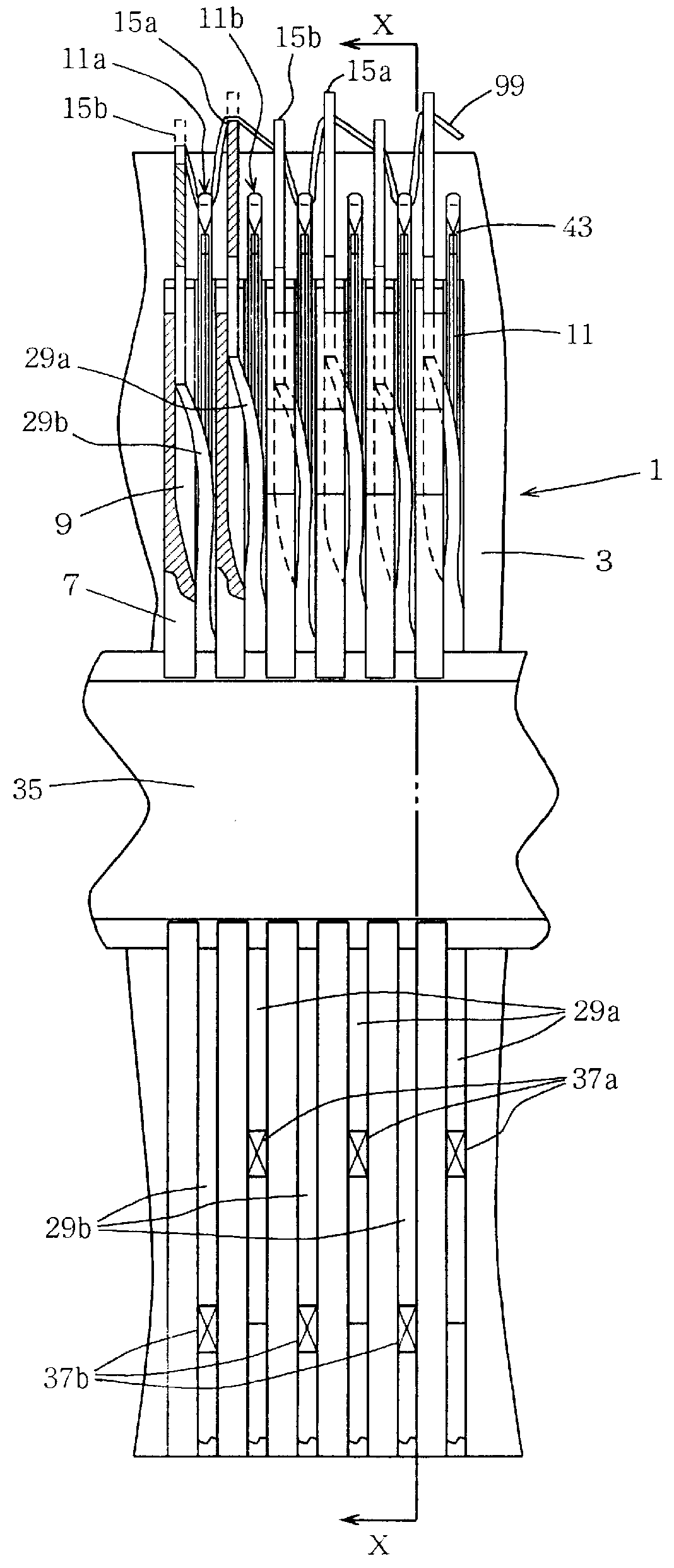
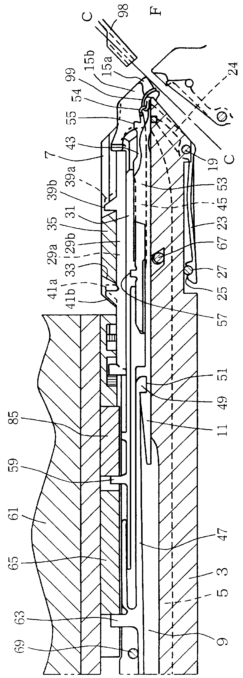
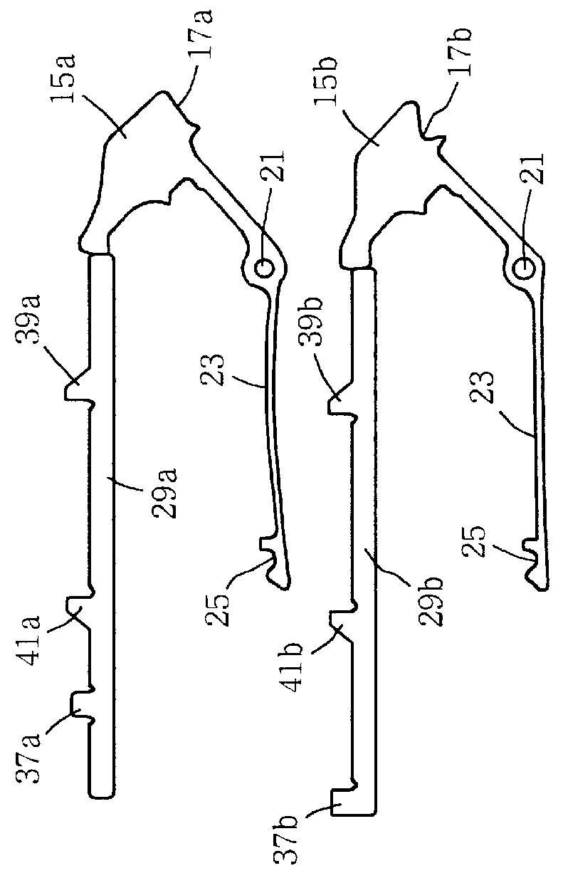
In the flat knitting machine of the first embodiment, needle plates 7 are provided in grooves 5 that are made in a needle bed base 3 at regular intervals. On a needle bed 1, a needle 11 is held in such a way that it can slide or move forward or backward in a concave needle groove 9 that is composed of sides of a pair of adjacent needle plates 7, 7 and the top of the needle bed base 3. A pair of needle beds 1, 1 are arranged to oppose to each other, one in the front and the other in the back, with the top ends of the needles 11 of one bed being close to those of the other bed. The first movable loop forming plate 15a and the second movable loop forming plate 15b, differing in configuration from each other, are alternately arranged between needles on the top ends of the needle beds 1, 1 on the trick gap side, over the entire longitudinal lengths of both the front and back needle beds 1, 1. The front and back needle beds 1, 1 are symmetrical, and only one needle bed will be described.

A...

second embodiment

The movable loop forming plate 305 makes a U-shaped portion 305, that is formed on one end thereof, contact the bottom 339 of the needle bed. With this arrangement, the loop forming edge 341 is energized in a direction that the loop forming edge 341 advances towards the center of the opening between both the front and back needle beds. In the middle of the movable loop forming plate 305, is formed a concave 343 that uses a wire 347, that is put through in the longitudinal direction of the needle bed, as the swing fulcrum to hold the movable loop forming plate 305. 345 is a wire that regulates the upward movement and the most retracted position of the movable loop forming plate 305 in the movable sinker groove 333. The wire 347 is held by a retainer 351 that is spanned between the wires 345,349 mounted on the bottom of the needle bed. The cam unit of the present embodiment is the cam unit 108 of the second embodiment to which cams for controlling the well-known movable sinker are add...


PUM


Abstract

Grooves for receiving a movable loop forming plate are made in both front and back needle beds at the top ends thereof on the trick gap side, and movable loop forming plates are mounted in the grooves. A loop forming edge is provided at the top end of each movable loop forming plate, and the plate is energized by a spring in a direction that the plate moves away from the trick gap, and the plate is made to move forward or backward by a movable loop forming plate control means, around a fulcrum that is provided on the needle bed in the bottom of the trick gap.

Description

The present invention relates to a flat knitting machine having at least a pair of a front needle bed and a back needle bed, said flat knitting machine is provided with movable loop forming plates between needles, said movable loop forming plate is provided with a loop forming edge that faces the opening between both the front and back needle beds on the trick gap side of the needle bed and said movable loop forming plate can be moved forward and backward between an advanced position in which the loop forming edge is advanced the most towards the opening between both the front and back needle beds and a retracted position in which the loop forming edge is retracted the most.PRIOR ARTA knitting method is disclosed in Japanese Patent Hei 3-75656, that is used when, on a flat knitting machine with two beds wherein a pair of needle beds are arranged to oppose, one in the front and the other in the back, a tubular fabric is formed with a front fabric and a back fabric being connected wit...

Claims


Application Information

Patent Timeline
Patent Type & Authority Patents(United States)
IPC IPC(8): D04B15/06D04B15/00D04B7/00D04B15/10D04B15/36
CPCD04B15/06D04B15/362D04B15/10D04B15/70D04B15/02D04B7/04D04B37/02
Inventor SHIMA, MASAHIRO
Owner SHIMA SEIKI MFG LTD
Why Eureka
Try Eureka