Light source device and projector

a light source device and projector technology, applied in the direction of picture reproducers using projection devices, instruments, semiconductor lasers, etc., can solve the problems of short life, large heating loss, low conversion efficiency of supplied power to optical power, etc., to avoid the accelerated progression of deterioration of semiconductor lasers

Active Publication Date: 2016-09-01
USHIO DENKI KK
View PDF12 Cites 13 Cited by
  • Summary
  • Abstract
  • Description
  • Claims
  • Application Information

AI Technical Summary

Benefits of technology

[0030]The present invention can provide a light source device and a projector which avoid an accelerated progression of deterioration of a semiconductor...

Problems solved by technology

However, the above-described high intensity discharge lamp has disadvantages such as low conversion efficiency from supplied power to optical power, that is, large heating loss, short life, or the like.
Among them, in the LED, as compared with the discharge lamp, the heating loss is small, and the life is long.
However, since light emitted from the LED does not have directivity similarly to the disch...

Method used


Image

  • Light source device and projector
  • Light source device and projector
  • Light source device and projector

Examples


Embodiment Construction

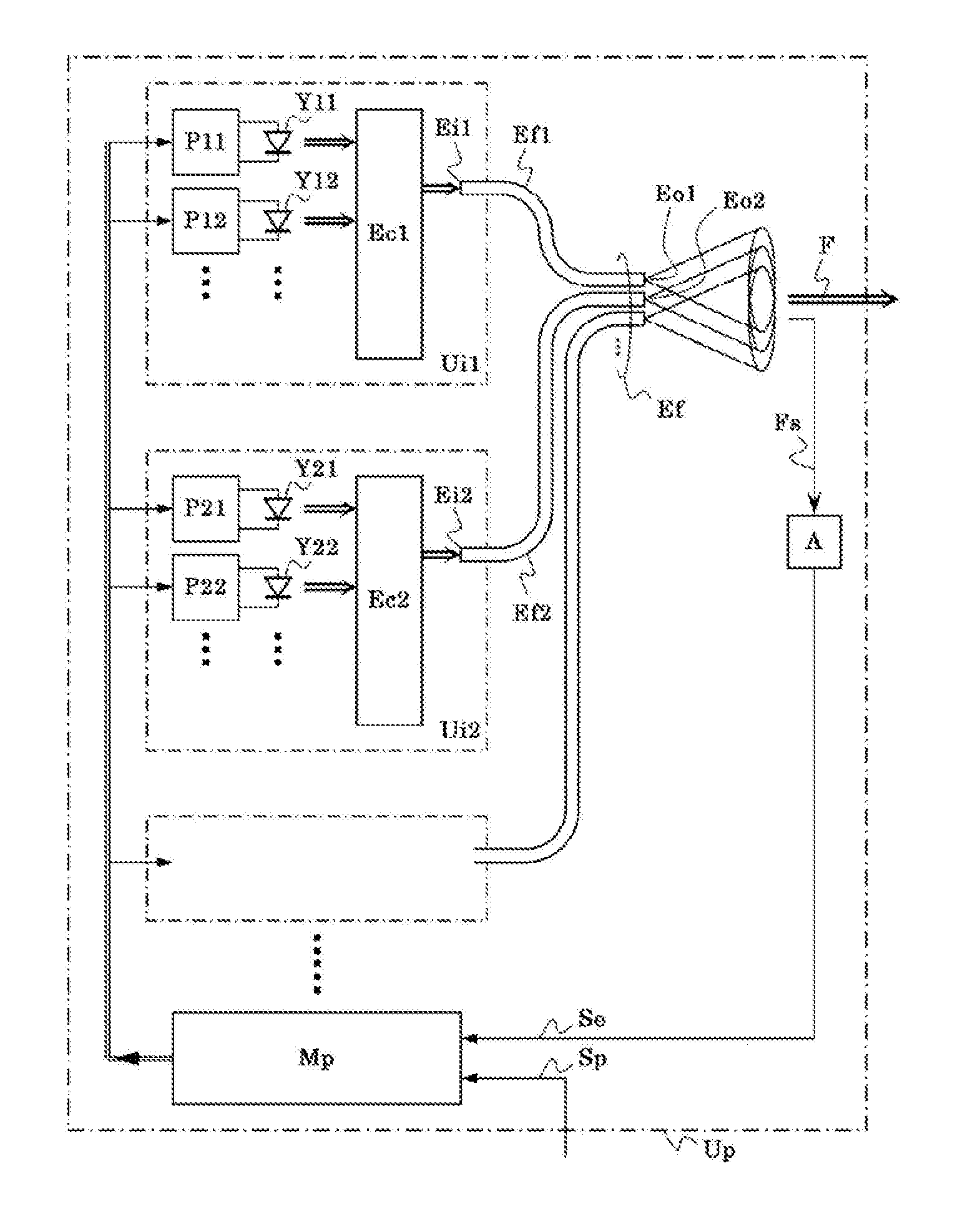
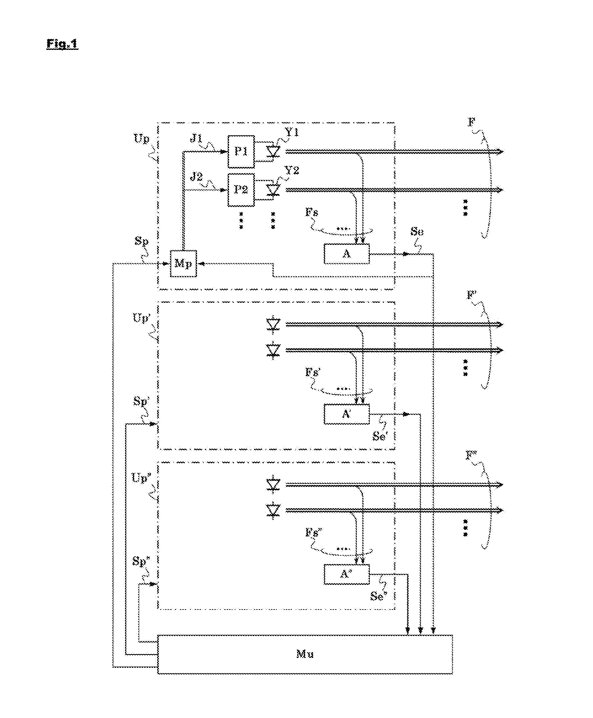
[0038]First, an embodiment for practicing the present invention will be described using FIG. 1, which is a block diagram showing a light source device of the invention in a simplified manner A deterioration controllable monochromatic light source module (Up) has light emitting elements (Y1, Y2, . . . ) each emitting light in a specific wavelength band, such as R, G, or B color, and the light emitting elements emit radiation luminous fluxes (F) to the outside. The light emitting elements (Y1, Y2, . . . ) are driven by drive circuits (P1, P2, . . . ) and the drive circuits (P1, P2, . . . ) are controlled by a light emission control circuit (Mp). Light intensity detection means (A) detects an amount of monitor light (Fs) taken as a portion of the radiation luminous flux (F) by a beam splitter or the like to generate a light intensity detection signal (Se), and, thus, to transmit the signal to the light emission control circuit (Mp).

[0039]Regarding the individual light emitting elements...


PUM


Abstract

To avoid accelerated progression of deterioration of a semiconductor laser, an LED, and the like to extend their lives while adjusting a balance of a plurality of colors, such as R, G, and B, by feedback control, a deterioration controllable monochromatic light source module is configured to: calculate a substantial upper limit Iu, determine an operation coefficient hx based on a deterioration coefficient dx, perform feedback control of the output current Ix of each drive circuit, and output a light intensity detection signal to the outside. An integrating control circuit calculates a monochromatic light intensity sum σ by a sum of light intensity detection signals from the monochromatic light source modules belonging to the same wavelength band and determines a light intensity target signal so that a ratio of the monochromatic light intensity sum σ to the monochromatic light source modules in different wavelength bands is a predetermined ratio.

Description

TECHNICAL FIELD[0001]The present invention relates to a light source device usable in an optical apparatus such as a projector, belonging to a plurality of types of different wavelength bands, and using a light emitting element such as a semiconductor laser.BACKGROUND ART[0002]For example, in a projector for image display, such as a DLP™ projector and a liquid crystal projector, and a photomask exposure apparatus, a high intensity discharge lamp (an HID lamp) such as a xenon lamp and a super-high pressure mercury lamp has been used. As an example, a principle of a projector is described using FIG. 6 (see JP-A-2004-252112, etc.). FIG. 6 is a view for explaining one embodiment of a portion of one type of conventional projector according to the projector of the present invention.[0003]As described above, light from a light source (SjA) formed of a high intensity discharge lamp or the like enters an incident end (PmiA) of light uniformizing means (FmA) with the help of focusing means (i...

Claims


Application Information

Patent Timeline
IPC IPC(8): H04N9/31H01S5/0687H01S5/042
CPCH04N9/3158H01S5/0687H01S5/042H04N9/3155G03B21/20G03B21/2013G03B21/2033G03B21/204G03B21/2053G03B21/206G03B21/208G03B33/06H01S5/4093H04N9/3161H04N9/3164H04N9/3182H04N9/3194H05B45/20H04N9/315
Inventor SAMEJIMA, TAKANORIODA, FUMIHIKOOKAMOTO, MASASHI
Owner USHIO DENKI KK
Why Eureka
Try Eureka