Ophthalmic lens with an optically non-coaxial zone for myopia control

a technology of optical non-coaxial zone and ophthalmic lens, which is applied in the field of ophthalmic devices, can solve the problems of hyperopia, eye growth is not enough, and the eye is not growing long enough, so as to slow down, retard or prevent myopia progression, and slow down the effect of myopia progression

Active Publication Date: 2019-07-25
JOHNSON & JOHNSON VISION CARE INC
View PDF2 Cites 50 Cited by
  • Summary
  • Abstract
  • Description
  • Claims
  • Application Information

AI Technical Summary

Benefits of technology

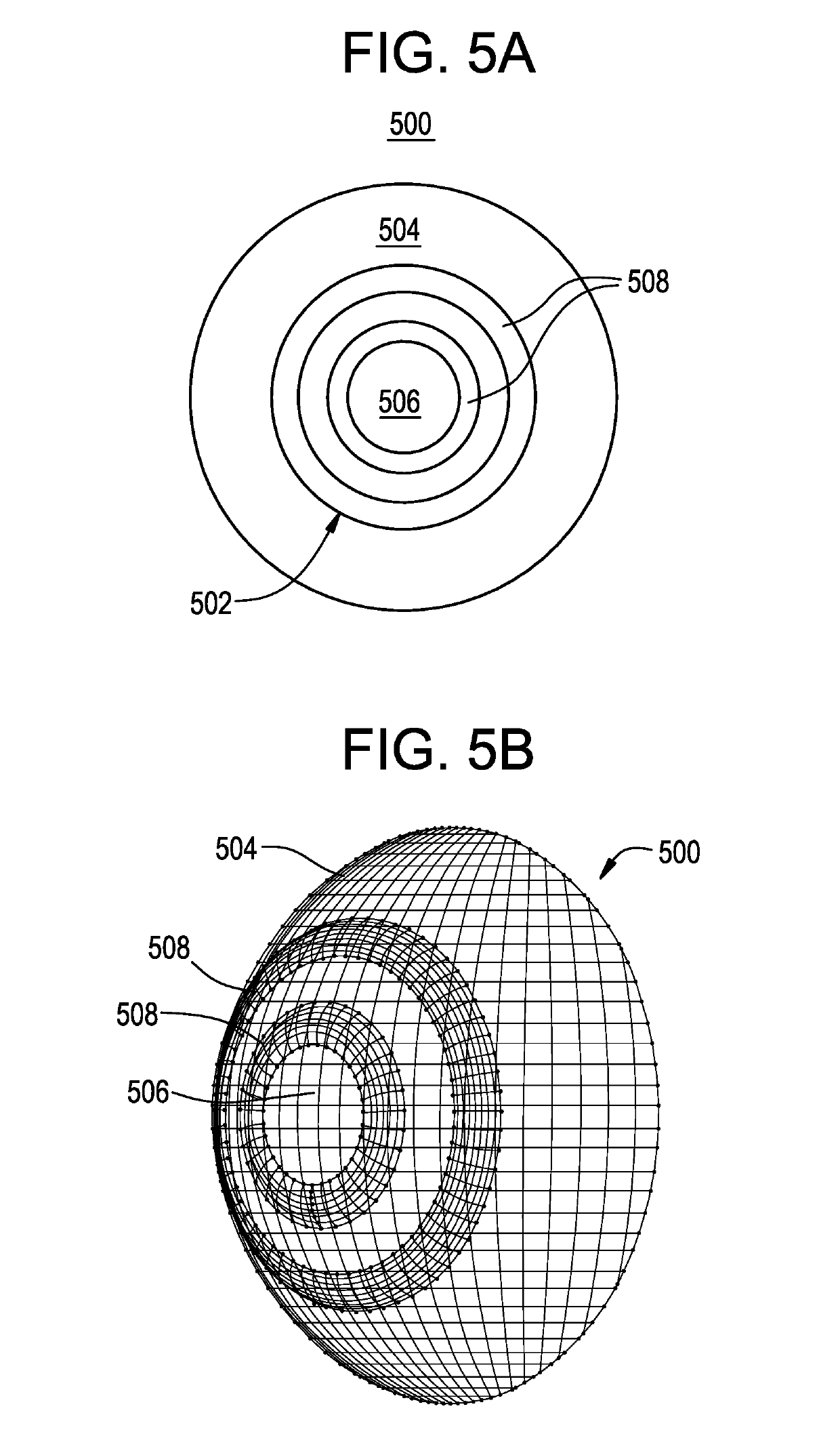
[0029]In accordance with one aspect, the present invention is directed to an ophthalmic lens for at least one of slowing, retarding or preventing myopia progression. The ophthalmic lens comprising a center zone with a negative power for myopic vision correction, and at least one treatment zone surrounding the center zone, the at least one treatment zone having a power profile comprising a positive power relative to the center zone, the at least one treatment zone having a surface shape comprising a portion of a generally toroidal shape, wherein the at least one treatment zone is arranged as to form a continuous surface with the center zone.
[0030]In accordance with another aspect, the present invention is directed to an ophthalmic lens for at least one of slowing, retarding or preventing myopia progression. The ophthalmic lens comprising a center zone with a negative power for myopic vision correction; and at least one treatment zone surrounding the center zone, the at least one treatment zone having a power profile comprising a positive power relative to the center zone, wherein the at least one treatment zone has an annular configuration having a shared radial center point with the center zone, and wherein the at least one treatment zone generates a focal ring, with the locus of each of the infinite focal points on the ring being displaced (‘non-coaxial’) from the geometric axis of the center zone, and wherein the at least one treatment zone is arranged as to form a continuous surface with the center zone.
[0031]In accordance with still another aspect, the present invention is directed to an ophthalmic lens for at least one of slowing, retarding or preventing myopia progression. The ophthalmic lens comprising a center treatment zone, a myopia correction zone surrounding the center zone, wherein the myopia correction zone exhibits a negative optical power for myopic vision correction, and wherein the center zone exhibits an ADD power relative to the myopia correction zone, and at least one treatment zone surrounding the center zone and disposed radially outwardly from the myopia correction zone, the at least one treatment zone having a power profile comprising a positive power relative to the myopia correction zone, wherein the at least one treatment zone has an annular configuration having a shared radial axis with the center zone, and wherein the at least one treatment zone generates a focal ring, with the locus of each of the infinite focal points on the ring being displaced ('non-coaxial') from the geometric axis of the center zone, and wherein the at least one treatment zone is arranged as to form a continuous surface with the center zone.
[0032]In accordance with still yet another aspect, the present invention is directed to an ophthalmic lens for at least one of slowing, retarding or preventing myopia progression. The ophthalmic lens comprising a center treatment zone, a myopia correction zone surrounding the center zone, wherein the myopia correction zone exhibits a negative power for myopic vision correction, and wherein the center zone exhibits an ADD power relative to the myopia correction zone, and at least one treatment zone surrounding the center zone and disposed radially outwardly from the myopia correction zone, the at least one treatment zone having a power profile comprising a positive power, the at least one treatment zone having a surface shape comprising a portion of a generally toroidal shape, wherein the at least one treatment zone is arranged as to form a continuous surface with the center zone.
[0033]In accordance with yet another aspect, the present invention is directed to an ophthalmic lens for at least one of slowing, retarding or preventing myopia progression. The ophthalmic lens comprising a center zone with a negative power for myopic vision correction, the center zone having a principal axis orthogonal to a surface thereof and passing through a center of the ophthalmic lens, and at least one treatment zone surrounding the center zone, the at least one treatment zone having a power profile comprising a positive power relative to the center zone, the at least one treatment zone having a surface shape comprising a portion of a generally toroidal shape, wherein the at least one treatment zone is arranged as to form a continuous surface with the center zone, and wherein the at least one treatment zone has a tilt angle configured to direct an innermost ray relative to a cross section of the treatment zone to cross the principal axis at a point that is at or anterior to a retinal plane of a wearer of the ophthalmic lens.
[0034]In accordance with another aspect, the present invention is directed to an ophthalmic lens for at least one of slowing, retarding or preventing myopia progression. The ophthalmic lens comprising a center zone with a negative power and exhibiting an on-axis focal point, and at least one treatment zone surrounding the center zone, the at least one treatment zone having a power profile comprising an ADD power relative to the center zone, the at least one treatment zone exhibiting a ring focus, wherein the power profile of the treatment zone comprises a curvilinear ramp configuration.

Problems solved by technology

Myopia typically develops because the axial length of the eye grows to be longer than the focal length of the optical components of the eye, that is, the eye grows too long.
Hyperopia typically develops because the axial length of the eye is too short compared with the focal length of the optical components of the eye, that is, the eye does not grow enough.
High myopia is also associated with an increased risk of retinal disease, cataracts, and glaucoma.
However, the corrective approach to the conditions does not address the cause of the condition, but is merely prosthetic or only addresses the symptoms.
Astigmatic errors of focus cause the image of a point source of light to form as two mutually perpendicular lines at different focal distances.
Blur with positive lenses, which leads to myopic blur, thickening of the choroid, and decrease in scleral growth rate, results in hyperopic refractive errors.
Blur with negative lenses, which leads to hyperopic blur, thinning of the choroid, and increase in scleral growth rate, results in myopic refractive errors.
One of the risk factors for myopia development is near work.
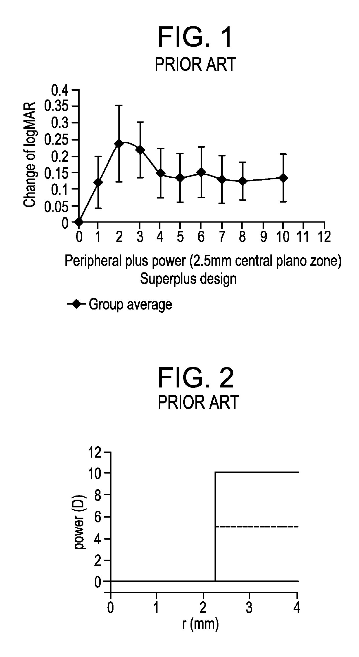
However, conventional wisdom in the field of bifocal or multifocal ophthalmic lenses assumes lenses with high plus or high ADD power may have deleterious effects on vision and contrast sensitivity as reported by Ardaya et al, Optometry 2004.
Further, significantly higher plus power relative to the power for providing clear distance vision is not expected to lead to reduced accommodation as may occur with a lower ADD power design where a subject might rely to some extent on that ADD power for clear vision during near work activities, as has been observed during the course of our research.
This reduced accommodation may lead to hyperopic defocus as a result of rays passing through the optical zones of the device that is for providing clear distance vision (distance portion of the device or myopia correction zone).
However, further optimization of ADD power designs is required to optimize image quality.
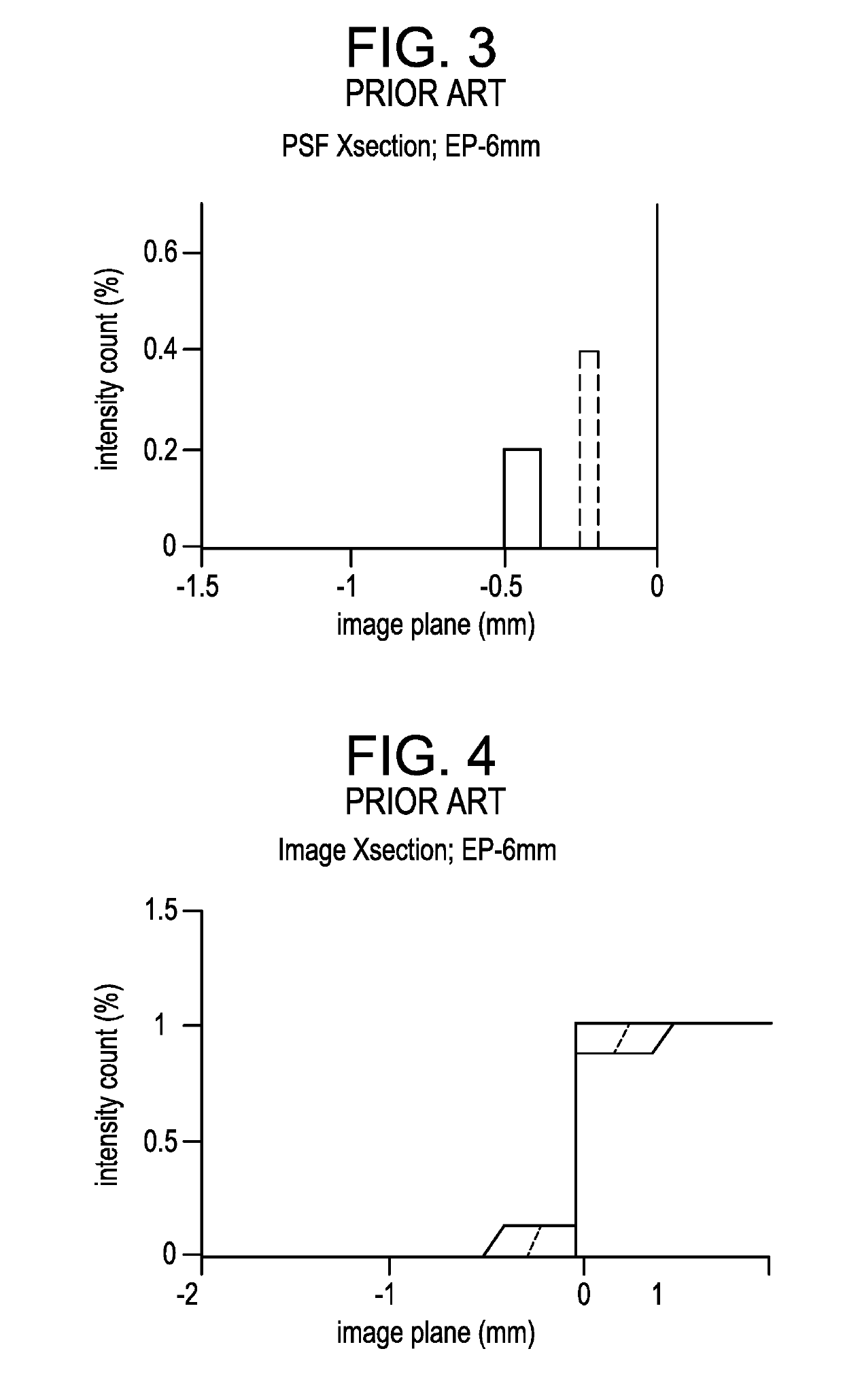
However, due to continued propagation to the retina, these rays form a ring-like defocus blur on the retina.
Nevertheless, this is a problem if a person looks at a black / white edge, as energy from the white background can leak into the black due to the presence of the spike in PSF.

Method used


Image

  • Ophthalmic lens with an optically non-coaxial zone for myopia control
  • Ophthalmic lens with an optically non-coaxial zone for myopia control
  • Ophthalmic lens with an optically non-coaxial zone for myopia control

Examples


Embodiment Construction

[0076]Ophthalmic devices may include implantable devices and / or wearable devices, such as contact lenses. Conventional contact lenses comprise polymeric structures with specific shapes to correct various vision problems.

[0077]As part of a typical eye examination the Eye Care Professional may determine the contact lens prescription required to correct the patients' refractive error. This prescription may specify the refractive power, cylindrical power, and / or cylinder axis of the contact lens, which may be used in determining the design or selection of a design of a contact lens.

[0078]Optical function of a radially concentric multizone ophthalmic lens that serves at least a spherical correction purpose is most generally derived from a front and back surface. One of these surfaces may be spheroidal or ellipsoidal in nature. The other surface typically has a spheroidal or ellipsoidal cap and then one or more curved portions, each of which is the surface of a spheroidal or ellipsoidal f...


PUM


Abstract

The present disclosure relates to ophthalmic devices such as ophthalmic lenses. An ophthalmic device may comprise an ophthalmic lens for at least one of slowing, retarding or preventing myopia progression. The ophthalmic lens may comprise a center zone with a negative power for myopic vision correction; and at least one treatment zone surrounding the center zone, the at least one treatment zone having a power profile comprising an ADD power, the at least one treatment zone having a surface shape comprising a portion of a generally toroidal shape, wherein the at least one treatment zone is arranged as to form a continuous surface with the center zone.

Description

BACKGROUND OF THE DISCLOSURE1. Field of the Disclosure[0001]The present disclosure relates to ophthalmic devices, such as wearable lenses, including contact lenses, implantable lenses, including inlays and onlays and any other type of device comprising optical components, and more particularly, to ophthalmic devices designed to slow, retard, or prevent myopia progression. The ophthalmic lenses of the present disclosure comprise at least one treatment zone with non-coaxial focus with ADD power, thereby preventing and / or slowing myopia progression.2. Discussion of the Related Art[0002]Ophthalmic devices, such as contact lenses, currently are utilized to correct vision defects such as myopia (nearsightedness), hyperopia (farsightedness), presbyopia and astigmatism. However, properly designed lenses may be utilized to enhance vision as well as to correct vision defects.[0003]Common conditions which lead to reduced visual acuity are myopia and hyperopia, for which corrective lenses in th...

Claims


Application Information

Patent Timeline
Patent Type & Authority Applications(United States)
IPC IPC(8): G02C7/04G02C7/06A61F2/14A61F2/16
CPCG02C7/044G02C7/06G02C7/048A61F2/1451A61F2/1613G02C2202/24A61F2230/0065A61F2002/1696G02C7/042G02C7/027A61F9/0017G02C7/02G02C7/047G02C7/045A61F2/16G02B1/043G02B3/0037G02C2202/12
Inventor BRENNAN, NOEL A.CHENG, XUHERNANDEZ, JACLYN V.COLLINS, MICHAEL J.DAVIS, BRETT A.YI, FANNANKIVIL, DEREK DEAN
Owner JOHNSON & JOHNSON VISION CARE INC
Why Eureka
Try Eureka