Integrated Gasification Combined Cycle and Operation Control Method Thereof

Active Publication Date: 2009-06-18
MITSUBISHI POWER LTD
View PDF3 Cites 16 Cited by
  • Summary
  • Abstract
  • Description
  • Claims
  • Application Information

AI Technical Summary

Benefits of technology

[0007]When the amount of air supplied to the gas turbine is decreased, the temperature therein is increased, and as a result, the operation is shifted to a temperature control mode. During this temperature control, in order to maintain an inlet temperature constant, since the output is reduced (C in FIG. 14), the amount of fuel gas flowing from the gasification furnace is decreased, and the pressure therein is concomitantly increased (D in FIG. 14).
[0032]The present invention provides advantages in that the balance of pressure / temperature in an overall plant can be adjusted and, during load variation, the output of the gas turbine can be stabilized at an early stage.

Problems solved by technology

One problem experienced in this IGCC is, for example, output variation of a gas turbine which occurs during load variation, as described below.

Method used


Image

  • Integrated Gasification Combined Cycle and Operation Control Method Thereof
  • Integrated Gasification Combined Cycle and Operation Control Method Thereof
  • Integrated Gasification Combined Cycle and Operation Control Method Thereof

Examples


first embodiment

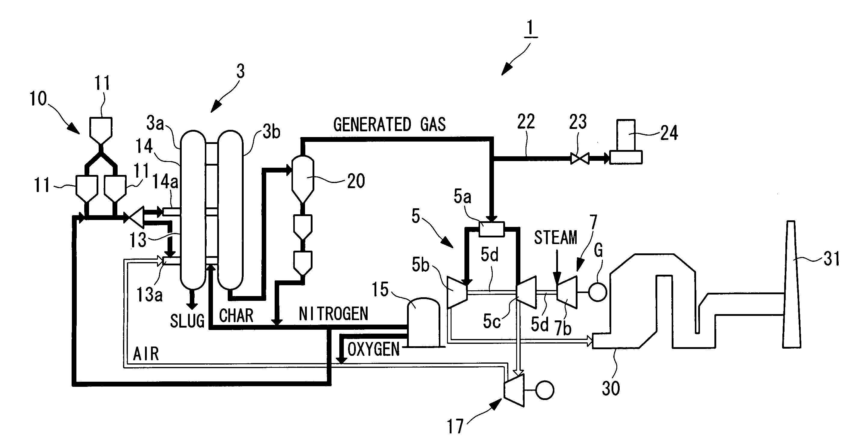
[0056]Hereinafter, an integrated gasification combined cycle (hereinafter referred to as “IGCC”) and a control operation method thereof, according to a first embodiment of the present invention, will be described with reference to the drawings.

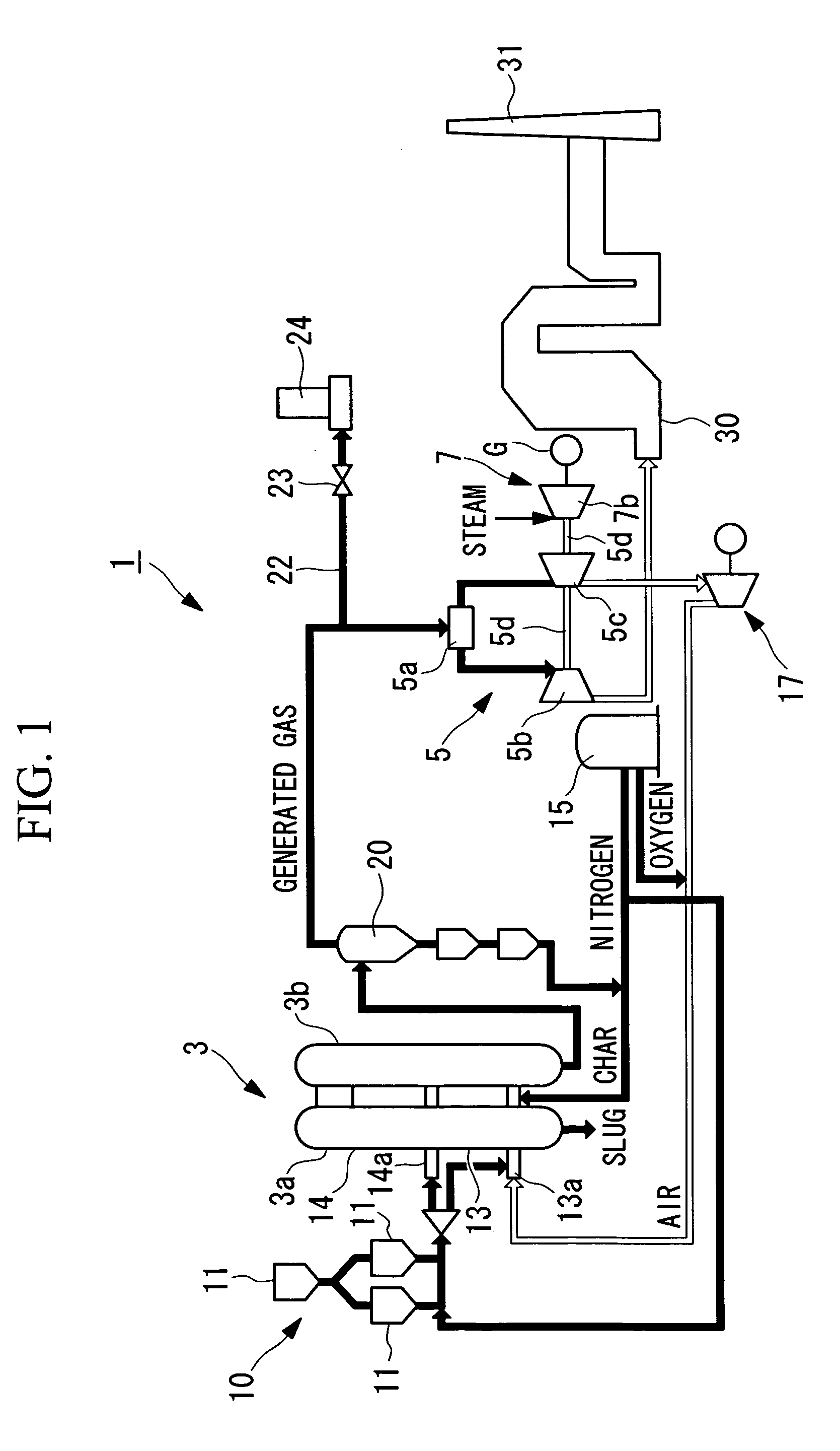
[0057]FIG. 1 is a view showing a schematic structure of the overall IGCC according to this embodiment.

[0058]As shown in FIG. 1, an IGCC 1 according to this embodiment primarily includes a gasification furnace 3, a gas turbine facility 5, a steam turbine facility 7, and an exhaust heat recovery boiler (HRSG) 30.

[0059]At the upstream side of the gasification furnace 3, a coal supply facility 10 for supplying powdered coal to the gasification furnace 3 is provided. This coal supply facility 10 includes a pulverizer (not shown) which pulverizes coking coal into powdered coal of several to several hundreds of micrometers, and the powdered coal pulverized by this pulverizer is stored in a plurality of hoppers 11.

[0060]The powdered coal stored in the...

second embodiment

[0118]Next, an IGCC and an operation control method thereof according to a second embodiment of the present invention will be described.

[0119]When a calorific abnormality of fuel gas is detected in the above first embodiment, the change rate setting unit 78 sets the change rate of the gas turbine output command GT_MWD to zero.

[0120]In this embodiment, as shown in FIG. 7, a pressure deviation ΔP obtained in the gasification furnace control apparatus 50, that is, the difference between the pressure command value set based on the gas turbine output command GT_MWD and the actual gasification furnace outlet pressure, is given to the change rate setting unit 78 of the gas turbine control apparatus 70, as shown in FIG. 8, and when the pressure deviation ΔP is larger than a standard value, the change rate setting unit 77 sets the change rate to zero.

[0121]With the structure described above, when the deviation between the gasification furnace outlet pressure and the pressure command value is...

third embodiment

[0123]Next, an IGCC and an operation control method thereof according to a third embodiment of the present invention will be described.

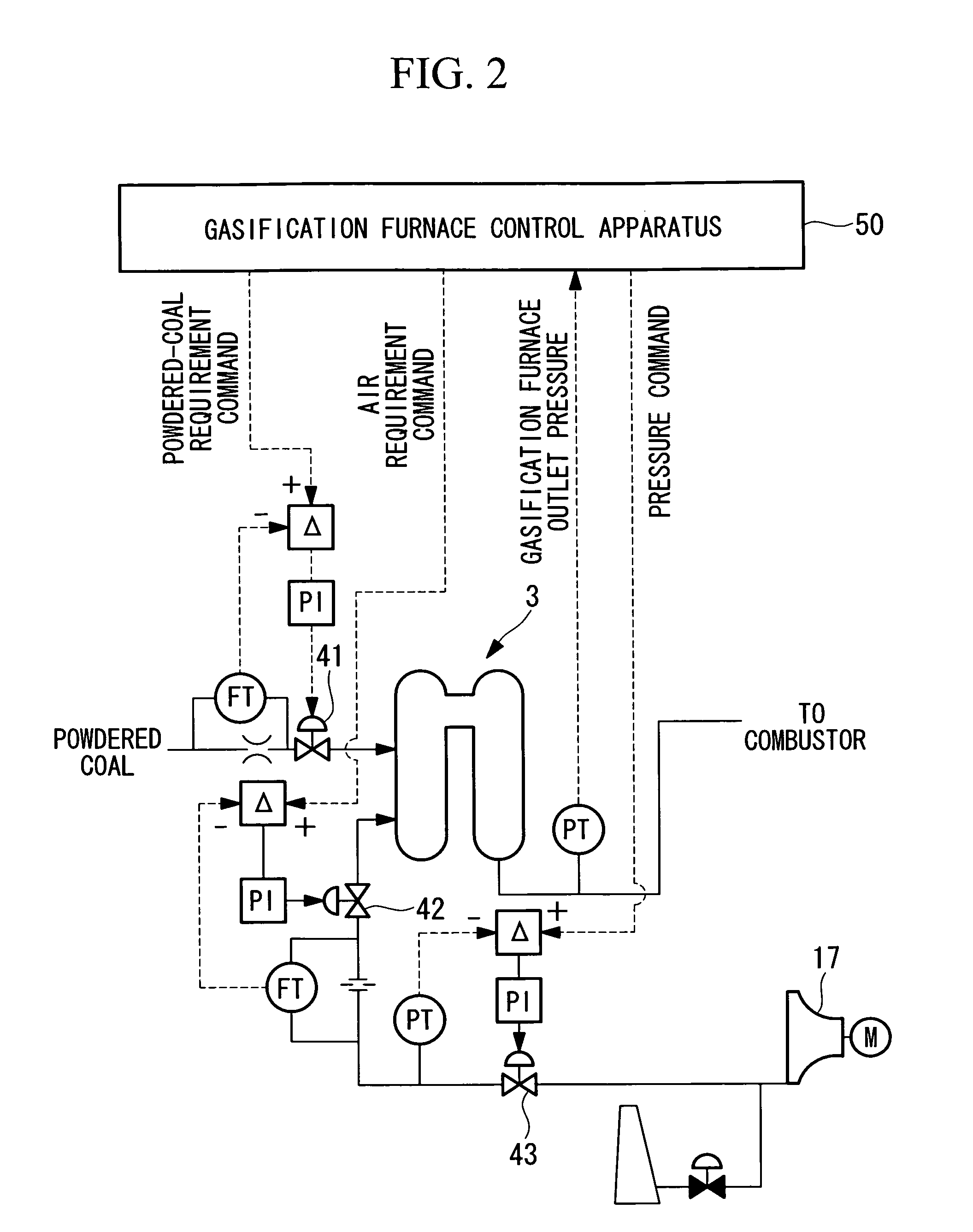
[0124]In the IGCC according to this embodiment, as shown in FIG. 9, the method for generating the powdered-coal requirement command and the method for generating the air requirement command in the gasification furnace control apparatus 50 are different from those of the first embodiment.

[0125]Hereinafter, differences from the first embodiment will be primarily described.

[0126]As shown in FIG. 9, in this embodiment, as in the first embodiment, by using a table in which GID and a powdered-coal capacity are related with each other, a coal required amount is first obtained, and by adding a coal acceleration command GIRfuel enhancing the operating conditions of the gasification furnace 3 to this carbon required amount, a final powdered-coal requirement command is generated. In this case, the coal acceleration command GIRfuel is a control value which is se...


PUM


Abstract

An integrated gasification combined cycle that can adjust the balance of pressure / temperature in an overall plant and can stabilize the output of a gas turbine at an early stage during load variation, and an operation control method of the integrated gasification combined cycle are provided. When a calorific abnormality of fuel gas is detected during load variation of a gas turbine (5b), a load change command value of the gas turbine (5b) is set to zero or is decreased, and based on this load change command value, a power generation output command of the gas turbine (5b) is generated.

Description

TECHNICAL FIELD[0001]The present invention relates to an integrated gasification combined cycle and an operation control method thereof.BACKGROUND ART[0002]Heretofore, an integrated gasification combined cycle (IGCC) that combines a gas turbine facility and a steam turbine facility has been known (for example, see Patent Document 1).[0003]Patent Document 1: Japanese Unexamined Patent Application, Publication No. 2002-129910DISCLOSURE OF INVENTION[0004]One problem experienced in this IGCC is, for example, output variation of a gas turbine which occurs during load variation, as described below.[0005]In general, the response speed of a steam turbine is low as compared to that of a gas turbine. Hence, as shown in FIG. 14, since the delay in response of the steam turbine is compensated for by the gas turbine during load variation, a gas-turbine output command overshoots (A in FIG. 14). During this overshoot, since a large amount of fuel gas must be supplied to the gas turbine, a large co...

Claims


Application Information

Patent Timeline
Patent Type & Authority Applications(United States)
IPC IPC(8): F02C9/00F02C6/00
CPCC10J3/723C10J3/86C10J2300/165C10J2300/1675Y02E20/16C10J2300/1687Y02E20/18F01K23/101C10J2300/1678
Inventor KAMOHARA, SATORUSONODA, TAKASHITAKASHIMA, YASUHIROKITAGAWA, YUICHIRO
Owner MITSUBISHI POWER LTD
Why Eureka
Try Eureka