Under the counter paper towel dispensing system

a paper towel and under-counter technology, applied in the field of sheet commodity dispensing system, can solve the problems of stability, difficulty in access, and inability to generally use the storage space of users, and achieve the effect of convenient use and accessibility

Inactive Publication Date: 2000-06-27
SMEGAL THOMAS V
View PDF15 Cites 28 Cited by
  • Summary
  • Abstract
  • Description
  • Claims
  • Application Information

AI Technical Summary

Benefits of technology

It is therefore an object of the present invention to provide a system for supporting paper towels or other dispensed sheet commodities in an unused, yet relatively easily accessible area of cabinet space.
It is another object of the present invention to provide a system dispensing paper towels which is more accessible and easier to use than prior art systems.

Problems solved by technology

Paper towel racks installed on cabinet doors block access to the interior of the cabinet, and the nature of the installation, wherein the rack must move when the door is opened, provides problems of stability.
On the other hand, racks mounted within the cabinet generally block the use of limited storage space; further, situated within the cabinet, the user generally has to bend under the cabinet and reach within same, providing difficulty in access.
It has been found that the space above the cabinet door, within the cabinet, is not generally utilized for storage by the user.
But with this mounting location, a traditional paper towel rack would require the user to still open the cabinet door, reach in and find the towel to be dispensed, and dispense same, providing some difficulty and effort.

Method used


Image

  • Under the counter paper towel dispensing system
  • Under the counter paper towel dispensing system
  • Under the counter paper towel dispensing system

Examples


third embodiment

An alternative design of the main body could include a "C" configured extruded plastic or metal body, arranged so that the lateral arms forming the "C" could form the bracket for installation to a beam dispensing with the necessity of separate "C" clamps. For more information, see the discussion of the third embodiment, below.

embodiment 30

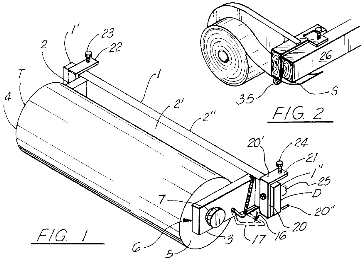
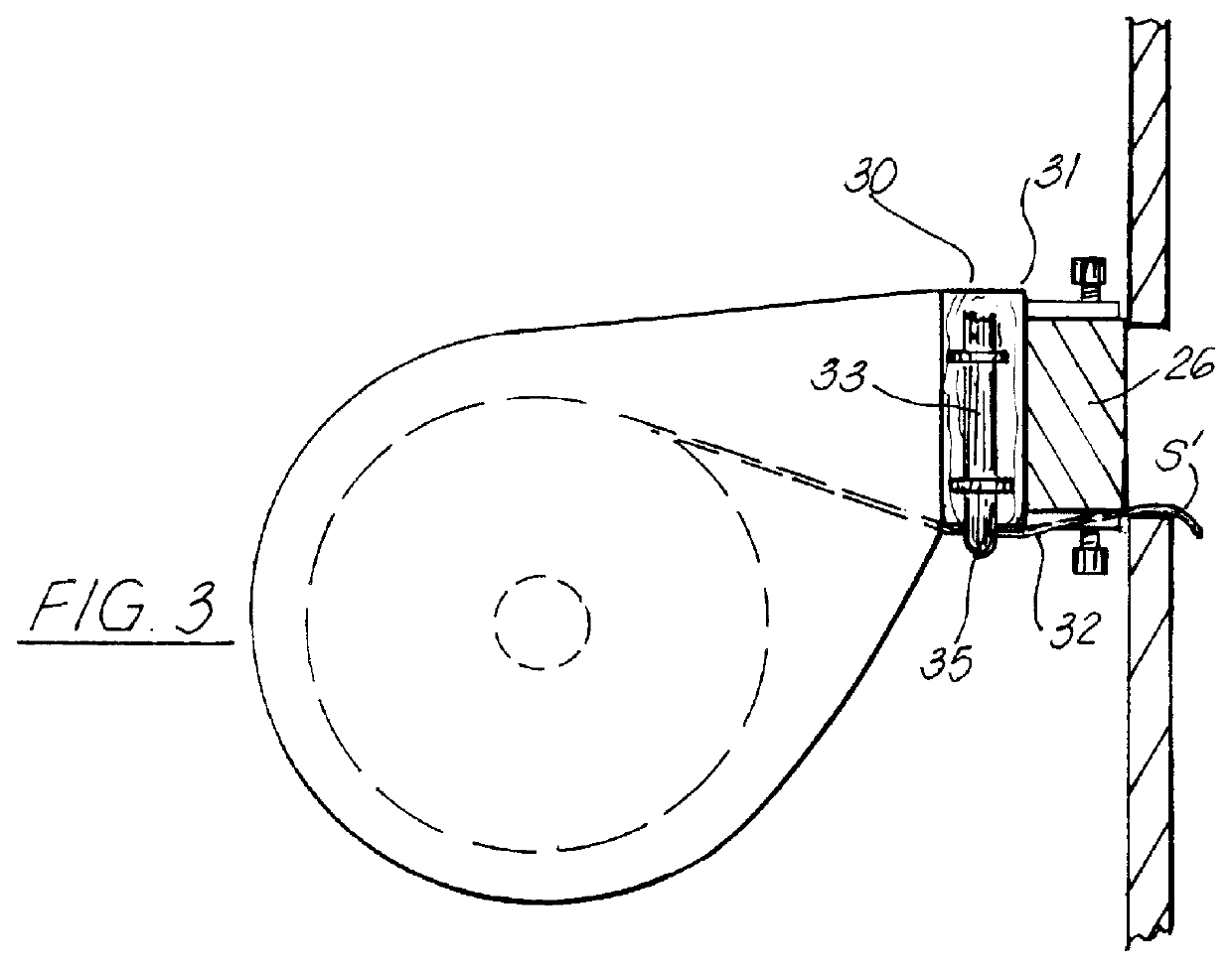
Referring to FIGS. 2, 3, and 5, an alternative embodiment 30 of the dispenser of the present invention utilizes an elastic cord to provide a holding means for retaining the sheet to be dispensed adjacent to the main body. As shown, the main body 30' has first 36 and second 37 ends, an upper edge 31 and a lower edge 32. An elastic member, which might comprise a 1 / 3 inch diameter, cloth covered elastic "bungee" cord or the like is provided having first 33 and second 34 ends, with a medial holding area 35 therebetween configured to engage the lower edge 32 of the main body, so that the sheet to be dispensed S may be placed therebetween to hold same in place. The elastic band E may be anchored to the main body via staples 39 or the like driven into the main body first and second ends, for example.

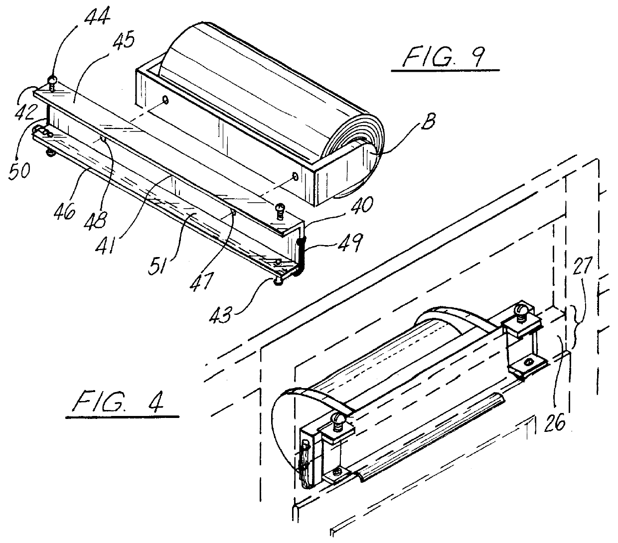
A third embodiment 40 of the present invention is shown in FIG. 9. As shown, the present invention may be provided in the form of a universal adapter bracket which is configured to engage and c...


PUM


Abstract

A paper towel dispensing rack designed for ease of installation and use, the preferred embodiment of the present system configured to be placed within the sink cabinet of kitchen cabinet, in such a manner that the rack is supported by a cabinet beam horizontally situated over the cabinet door. Unlike prior art systems, the rack of the present system supports the sheet to be dispensed such that it is easily accessible through a closed door, upon opening the door, as desired, but without the towel roll and rack blocking access to the cabinet or taking up unwanted space. The preferred embodiment of the invention utilizes a c-clamp structure to secure the rack to a horizontal beam commonly found in most kitchen cabinets supporting a sink, mounting the rack in a secure, yet removable fashion. The present system contemplates a towel holder mechanism to suspend at least a portion of the towel to be dispensed in a generally horizontal fashion, teaching a first embodiment utilizing a spring biased holding bar, and a second embodiment contemplating an elastic holder member.

Description

The present invention relates to sheet dispensers, and in particular to a paper towel dispensing rack designed for ease of installation and use, the preferred embodiment of the present system configured to be placed within the sink cabinet of kitchen cabinet, in such a manner that the rack is supported by a cabinet beam horizontally situated over the cabinet door. Unlike prior art systems, the rack of the present system supports the sheet to be dispensed such that it is easily accessible through a closed door, upon opening the door, as desired, but without the towel roll and rack blocking access to the cabinet or taking up unwanted space.The preferred embodiment of the invention utilizes a c-clamp structure to secure the rack to a horizontal beam commonly found in most kitchen cabinets supporting a sink, mounting the rack in a secure, yet removable fashion.The present system contemplates a towel holder mechanism to suspend at least a portion of the towel to be dispensed in a general...

Claims


Application Information

Patent Timeline
Patent Type & Authority Patents(United States)
IPC IPC(8): A47K10/24A47K10/38
CPCA47K10/38Y10T225/10Y10T225/393
Inventor SMEGAL, THOMAS V
Owner SMEGAL THOMAS V
Why Eureka
Try Eureka