Data processing form using a scanning apparatus

Inactive Publication Date: 2000-06-27
WILLIAM C APPERSON
View PDF6 Cites 77 Cited by
  • Summary
  • Abstract
  • Description
  • Claims
  • Application Information

AI Technical Summary

Problems solved by technology

If the skunk mark pattern for a new form has not been programmed into these devices, the scanner will reject the form as unrecognizable.
These devices usually have been designed with limited versatility and do not easily handle additional test forms compatible w

Method used


Image

  • Data processing form using a scanning apparatus
  • Data processing form using a scanning apparatus
  • Data processing form using a scanning apparatus

Examples


Embodiment Construction

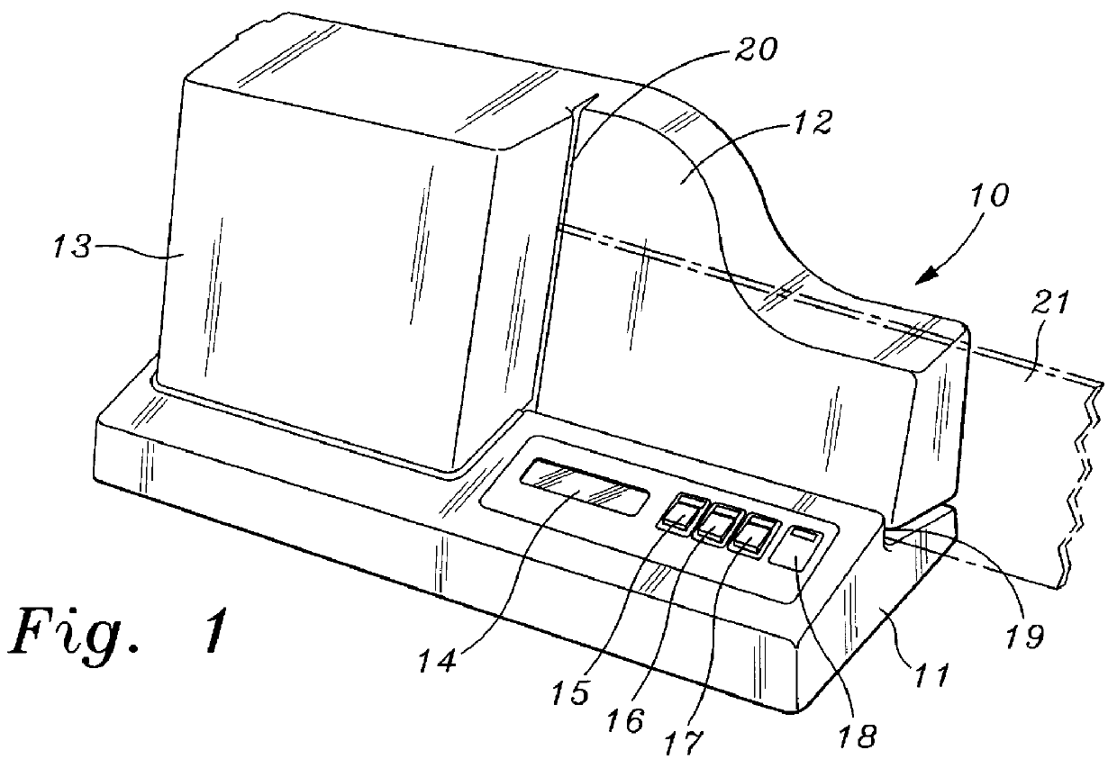
Referring now to FIG. 1, there is shown a front, perspective view of the scanner 10 of the instant invention. The scanner 10 includes a base 11, a back support 12 and a housing 13. The back support 12 is used, inter alia, to support a form or document 21 (shown dashed) which is to be scanned by the system. The housing 13 is, typically, a removable housing which is used to cover the actual scanning apparatus as described hereinafter.

A channel 19 is formed between the base 11 and the back support 12 to receive an edge of the form 21.

A slot 20 is formed between the back support 12 and the housing 13 so that the form 21 can be passed therethrough adjacent to the scanning mechanism described hereinafter.

A display 14 of any suitable type, such as light emitting diodes (LED's) or the like, is used to provide information to the user, as described hereinafter.

In addition, the control buttons 15, 16 and 17 are used to cause the scanner to display totals (for example, count totals on a form; r...


PUM


Abstract

This invention is directed to an optical mark sensing device known as a mark read scanner for reading marks on a form. This scanner is a stand-alone device that has an internal micro-controller with the controlling software therein. An external personal computer is not required to operate the scanner in its intended manner. "Graphic switches" are printed on the form to define the characteristics of a form to be scanned. The expense of replacing the internal program of a scanner when a user requests a variation of a test form that had not been pre-programmed into the original specifications of the scanner is eliminated.

Description

1. Field of the InventionThis invention relates to an optical mark sensing device known, in general, as a mark read scanner and to a stand-alone device which has an internal micro-controller with internally stored driving software and graphic switches on forms associated therewith, in particular.2. Prior ArtMark read scanners are used in a variety of data collection applications. The forms used with mark read scanners are commonly referred to as "bubble" or optical mark read (OMR) forms on which the user fills in a bubble on the form, typically, with a number 2 lead pencil.Present mark read test scoring devices and mark interpretation software use a binary system for describing the absence or presence of a mark. These systems are limited to the presence / absence or on / off binary sequence. Thus, very large numbers of codes are needed in order to read a relatively large number of marks. Mark positions are, typically, assigned digital values between "0" and "255" at the start of the pro...

Claims


Application Information

Patent Timeline
IPC IPC(8): G06K17/00
CPCG06K17/0032
Inventor APPERSON, WILLIAM C.BECK, COURTLAND G.
Owner WILLIAM C APPERSON
Why Eureka
Try Eureka