Putter head with improved alignment and stability features

a technology of stability and putter head, which is applied in the field of putter, can solve the problems of reducing the forward momentum of the putter, causing the player to miss the putt, and causing the troublesome area of the putter

Inactive Publication Date: 2000-06-27
AKRIBIS GOLF COMPANY LLC DBA TRAXX PUTTERS
View PDF4 Cites 75 Cited by
  • Summary
  • Abstract
  • Description
  • Claims
  • Application Information

AI Technical Summary

Benefits of technology

It is another object of the present invention to achieve the foregoing object by providing a groove and a pair of rails clearly viewable in low-light conditions and over a wide range of angles on the putter head so that a golfer will know that the head is properly aligned when the groove is oriented in a desired manner relative to the rails.
It is another object of the present invention to provide a putter head having rails which are substantially flat so as to impart horizontal stability to the putter during a putt.
It is another object of the present invention to provide a golf putter head having a structure which prevents grass or other putting surface objects from interfering with the putter head during a putt.
Advantageously, the present invention overcomes the shortcomings of conventional putter heads by providing a wide viewing aperture and a rear portion on the putter head that is shorter than the putting face, thus allowing more light to illuminate the rails. Also, the rails of the present invention are flat on the bottom to impart horizontal positional stability and alignment to the putter head during a putt. The putter head of the present invention thus gives a golfer a clearer view of the rails during putting than do conventional putter heads and imparts greater stability when contacting a putting surface.
During the initial setup, a player places the putter head on the putting surface behind the ball so that both rails on the bottom of the putter head lie flat and level on the putting surface while the golfer is looking through the aperture. When the rails are in this position, a player is assured that the putter head is lying in a parallel and stable position relative to the ground. Next, the golfer positions himself in such a manner that the groove on top of the putting face is between and preferably centered relative to the two rails from a golfer's line-of-sight perspective. When oriented in this manner, the player is oriented directly over the putter head. As a result, the player is assured that the putting face is perpendicular to the intended travel path of the ball and that his eyes are positioned directly above the ball target fine.
Further, during the forward swing, any grass or other putting surface obstructions that might reduce the momentum of the putter will advantageously be deflected by the rails on the putter head. Further, gaps between and to the sides of the rails allow the grass to pass without imparting any loss of momentum, and if the forward putter stroke is too low, the shape of the rails will reduce any loss of due to contact with the putting surface.

Problems solved by technology

In many instances, putting is a troublesome area for these players.
Striking the ball when the putter face is misaligned with the intended ball path or when the putter bottom is not level with the putting surface often causes putts to be missed.
In many instances, during the forward stroke, the putter head encounters grass or even the putting surface which reduces the forward momentum of the putter.
This results in an inconsistent or jerky stroke and ultimately a missed putt.
U.S. Design Patent 291,464 and U.S. Design Patent Application 29 / 090,058 disclose two examples, however, both designs have proved to be ineffective.
Furthermore, the rails are rounded and thus do not impart horizontal stability to the putter head when resting on the putting surface.

Method used


Image

  • Putter head with improved alignment and stability features
  • Putter head with improved alignment and stability features
  • Putter head with improved alignment and stability features

Examples


Embodiment Construction

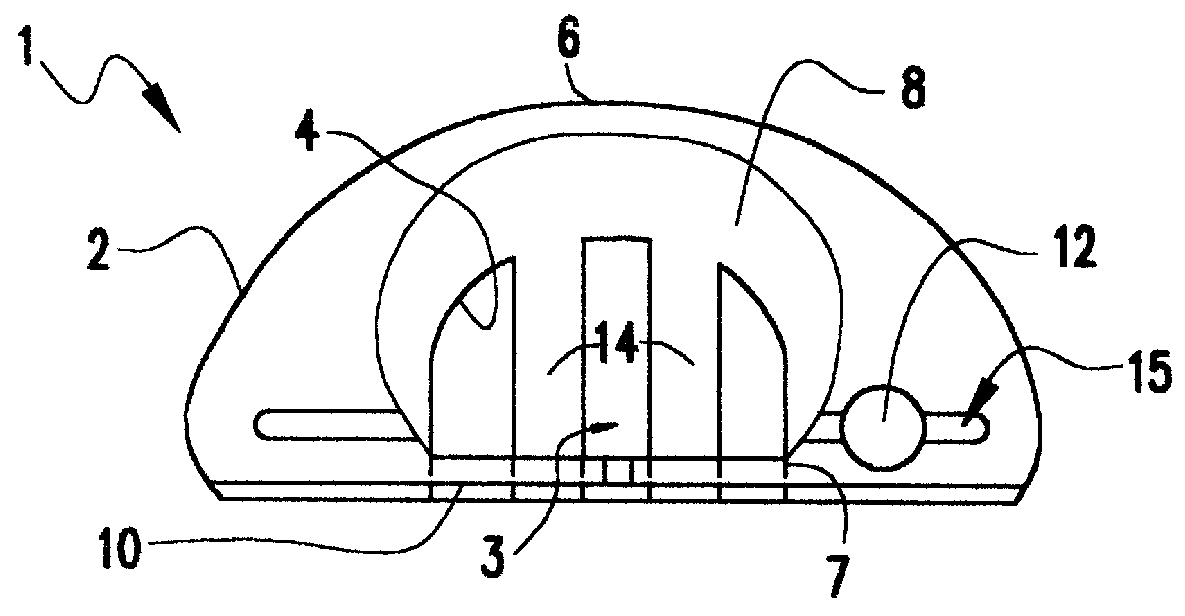
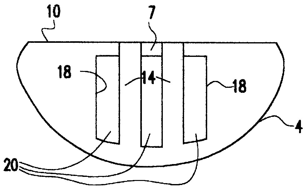
Referring now to the drawings, FIG. 1 shows a top view of a preferred embodiment of the putter head 1 of the present invention wherein a putter body 2 has a perimeter preferably with a semi-elliptical shape and a semi-circular aperture 4 extending through a central portion 3. A putting face 10 is formed on a front portion 7 of the putter body 2. A hole 12 is provided in the putter body 2 for receiving a shaft (not shown). Visible through aperture 4 are a pair of rails 14 that extend from a bottom portion 9 of the putting face 10 across aperture 4 and connect to a bottom 11 of the rear portion 6 of the putter body 2. Advantageously, rear portion 6 of the putter body 2 has sides 8 which are rounded to allow even more light to enter the aperture 4. A slot 15 extends along the top of the front portion 7 of the putter body 2, parallel with the putting face 10.

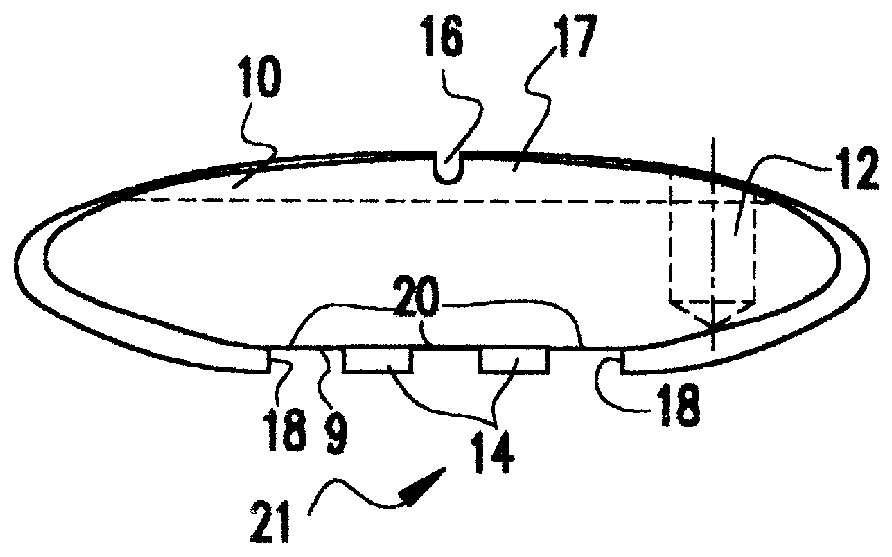
FIG. 2 shows a front view of putter head 1 wherein the putting face 10 has a top portion 17 containing a groove 16. FIG. 2 also sh...


PUM


Abstract

A putter head includes an aperture through which two rails extending across a bottom of the putter head can be viewed. After establishing a target line, the player first levels the rails flat on the putting surface. Then, the player looks down on the putter head and adjusts his position and aligns the putter head in such a manner that a groove on top of the putter is seen as situated / centered between the rails. A slot running parallel to the putting face of the putter head also is used to ensure that the putter head is in proper alignment. Also, the rails are substantially flat to impart additional horizontal stability and alignment to the putter head during putting.

Description

1. Field of the InventionThe invention generally relates to a putter, and more particularly to a putter head having features which aid a golfer in setting up and executing a putt.2. Description of the Related ArtIn recent years, the popularity of golf has increased, which in turn has led to an increase in the number of novice players entering the sport as well as veteran players wishing to improve their game. In many instances, putting is a troublesome area for these players.Successful putting requires striking a golf ball in such a way that it will travel along a path that leads to the cup. In order to execute a good putt, a player must properly setup and aim the putter, and then execute a consistent putting stroke. To setup a putt, a player will choose the path along which he or she wishes the ball to be directed. Next, the player positions him or herself in correct relation to the golf ball (usually facing perpendicular to the intended path of the ball). During the execution of a...

Claims


Application Information

Patent Timeline
Patent Type & Authority Patents(United States)
IPC IPC(8): A63B53/04
CPCA63B53/0487A63B49/06A63B59/0088A63B2053/0441A63B2053/0433A63B60/50A63B60/52A63B53/0433A63B53/0441
Inventor WHITLEY, TIM A.
Owner AKRIBIS GOLF COMPANY LLC DBA TRAXX PUTTERS
Why Eureka
Try Eureka