

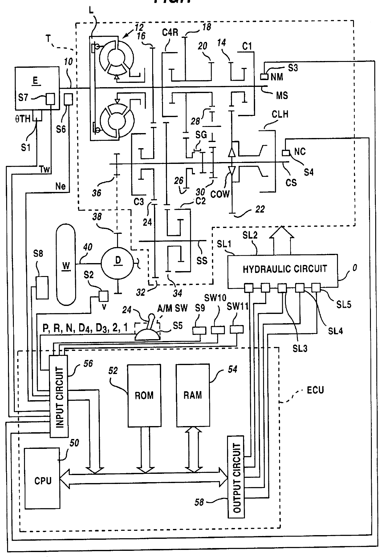
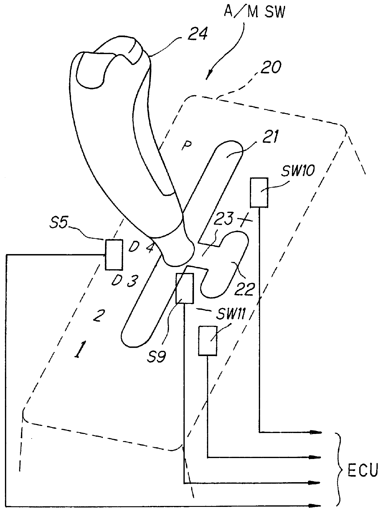
Control system for automatic vehicle transmission
a technology for automatic vehicles and transmission systems, applied in mechanical devices, instruments, transportation and packaging, etc., can solve the problems of difficult for drivers to obtain the desired gear, difficult for drivers to move the shift lever frequently, and achieve the effect of achieving the desired gear
- Summary
- Abstract
- Description
- Claims
- Application Information
AI Technical Summary
Problems solved by technology
Method used
Image

Examples
second embodiment
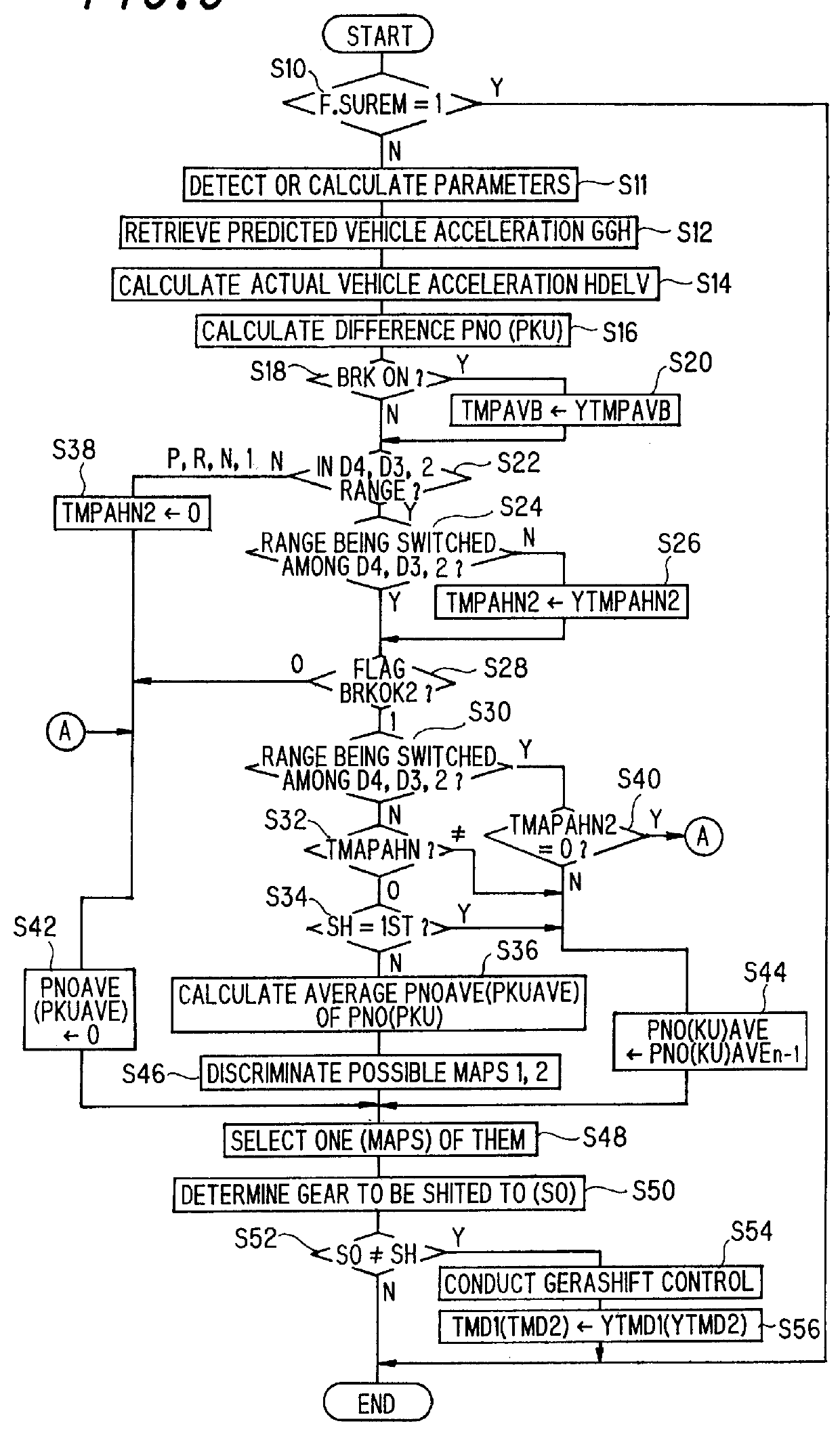
FIG. 18 is a view, similar to FIG. 14, but showing the system according to the invention.
In the second embodiment, the program begins in S800 in which the average value of the difference in hill-climbing PNOAVE is compared with a prescribed value PNO21 (the threshold value for the steep-hill climbing (MAPS 4) illustrated in FIGS. 7 and 8). In other words it is determined in S800 whether the running condition is such that the steep-hill climbing map (MAPS 0) is selected.
When the result in S800 is negative, the program proceeds to S802 in which a predetermined vehicle speed VTPRO is made zero, to S804 in which VTA43 is determined to be YVTA43 (threshold value for level-road running). On the other hand, when the result in S800 is affirmative, the program proceeds to S806 in which it is determined whether current gear SH is 4th. When the result is affirmative, the program proceeds to S808 in which the detected vehicle speed V is compared with the value VTPRO. Since VTPRO was set to zero...
PUM
 Abstract
Description
Claims
Application Information