Roll-biased head suspension for reduced track misregistration

Inactive Publication Date: 2000-07-11
MAXTOR
View PDF6 Cites 54 Cited by
  • Summary
  • Abstract
  • Description
  • Claims
  • Application Information

AI Technical Summary

Benefits of technology

Another object of the present invention is to provide a method and apparatus for adding a roll-bias to a data transducer suspension assembly in a hard disk drive in a manner reducing TMR during out-of-plane motions of a storage disk in a manner overcoming limitations and drawbacks of the

Problems solved by technology

Faster disk rotation has the undesirable drawback of potentially exciting one or more disk resonance modes by virtue of increased air turbulence, or by coupling vibrations through spindle bearings, for example.
Moreover, the article does not address the kinematics and structural causes of disk-vibration-induced TMR and it presents no solutions to correct for the resultant TMR.
These effects are difficult to control, and

Method used


Image

  • Roll-biased head suspension for reduced track misregistration
  • Roll-biased head suspension for reduced track misregistration
  • Roll-biased head suspension for reduced track misregistration

Examples


Embodiment Construction

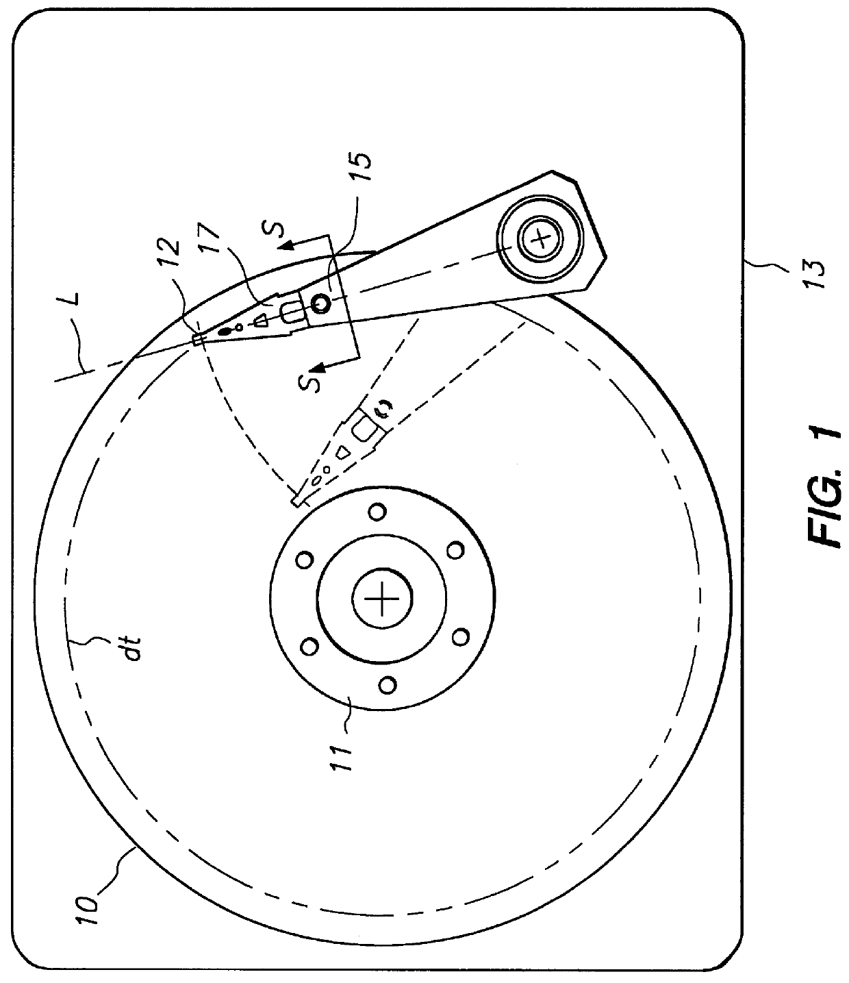
A disk drive HDA as shown in FIG. 1 is improved by addition of roll-bias in

order to reduce TMR caused by out-of-plane movements of the storage disk 10 in response to one or several ones of many potential sources of vibrational or shock energy forces. Roll bias is applied relative to a plane of the head arm 15 along a longitudinal axis L. The head arm arrangement shown in FIG. 1 is known in the art as an "in-line" rotary voice coil actuator in which the load beam 17 extends in alignment along the axis L from an end of the head arm 15 of the actuator E-block structure to an axis of rotation of the voice coil actuator

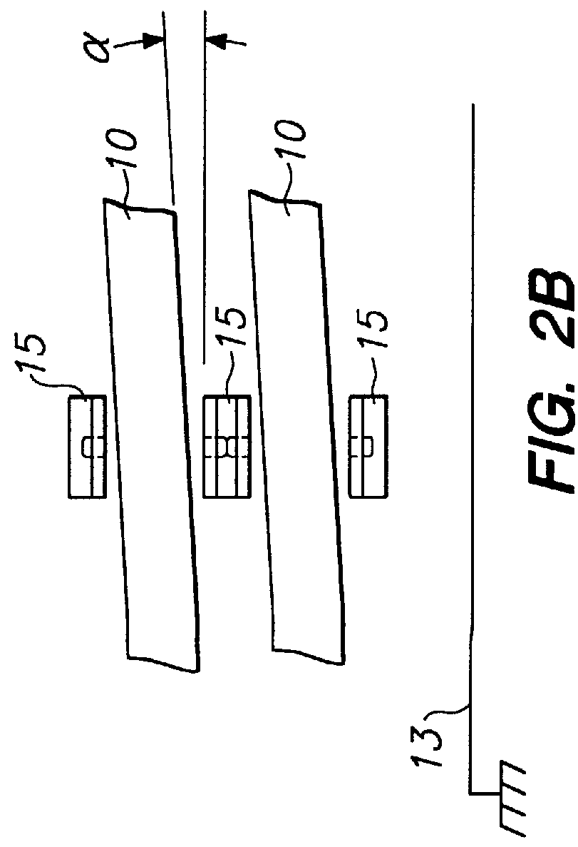
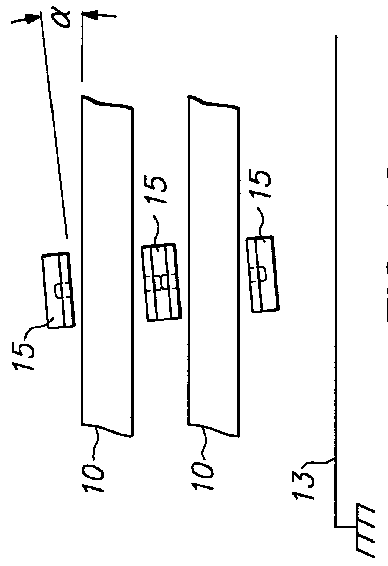
As shown in FIG. 2A, a nominal parallel alignment is desired between a stack 10 of storage disks, and a head arm structure 15, as referenced to the base 13. In the situation of perfect parallelism between the disks 10 and actuator 15 as established by base 13, some disk radial and out-of-plane deflection will couple to TMR because of an inherent response structurally of th...


PUM


Abstract

A method corrects track misregistration attributable to out-of-plane motions of a rotating disk in a hard disk drive, and includes the steps of measuring a base plate-roll-bias angle between the rotating data storage disk and the head arm with a precision measuring device, and connecting the head arm and load beam at a roll-bias angle selected to minimize track misregistration attributable to the roll-bias. A number of connection arrangements and structures are presented in order to achieve the desired reduction in track misregistration.

Description

FIELD OF THE INVENTIONThe present invention relates to hard disk drives. More particularly, the present invention relates to a head suspension which has been roll-biased for minimizing head / disk track misregistration caused by out-of-plane motion of a storage disk relative to a nominal plane of rotation.BACKGROUND OF THE INVENTIONA hard disk drive typically comprises a rotating data storage disk 10 and a read / write head transducer assembly including a slider 12 and an electromagnetic read / write transducer unit carried by the slider 12. A plan view of a disk drive of this type is shown in FIG. 1. The slider 12 is positioned radially relative to the rotating disk 10 by a head arm assembly 15, so that write and read elements follow a data track (dt) defined on a storage surface of the disk 10, there being a multiplicity of available concentric data track locations on the surface. The head arm assembly is moved to track (dt) by e.g. a rotary voice coil motor, not shown in FIG. 1.During ...

Claims


Application Information

Patent Timeline
IPC IPC(8): G11B33/10G11B33/00G11B5/48G11B5/58G11B21/16
CPCG11B5/4813G11B5/4833G11B5/4886G11B5/58G11B33/10G11B5/596G11B2220/2516
Inventor RIENER, TIMOTHY A.LOW, JAMES MONTGOMERYJACOBY, JON EDWARDHATCH, MICHAEL R.WILLIAMS, STEPHEN P.
Owner MAXTOR
Why Eureka
Try Eureka