Filter alert

a filter and alert technology, applied in the field of alerts, can solve problems such as the existence of monitoring filter conditions

Inactive Publication Date: 2000-08-01
CHAMPIE MAX C
View PDF8 Cites 28 Cited by
  • Summary
  • Abstract
  • Description
  • Claims
  • Application Information

AI Technical Summary

Problems solved by technology

Problems with monitoring filter conditions continue to exist.

Method used


Image

  • Filter alert
  • Filter alert
  • Filter alert

Examples


Embodiment Construction

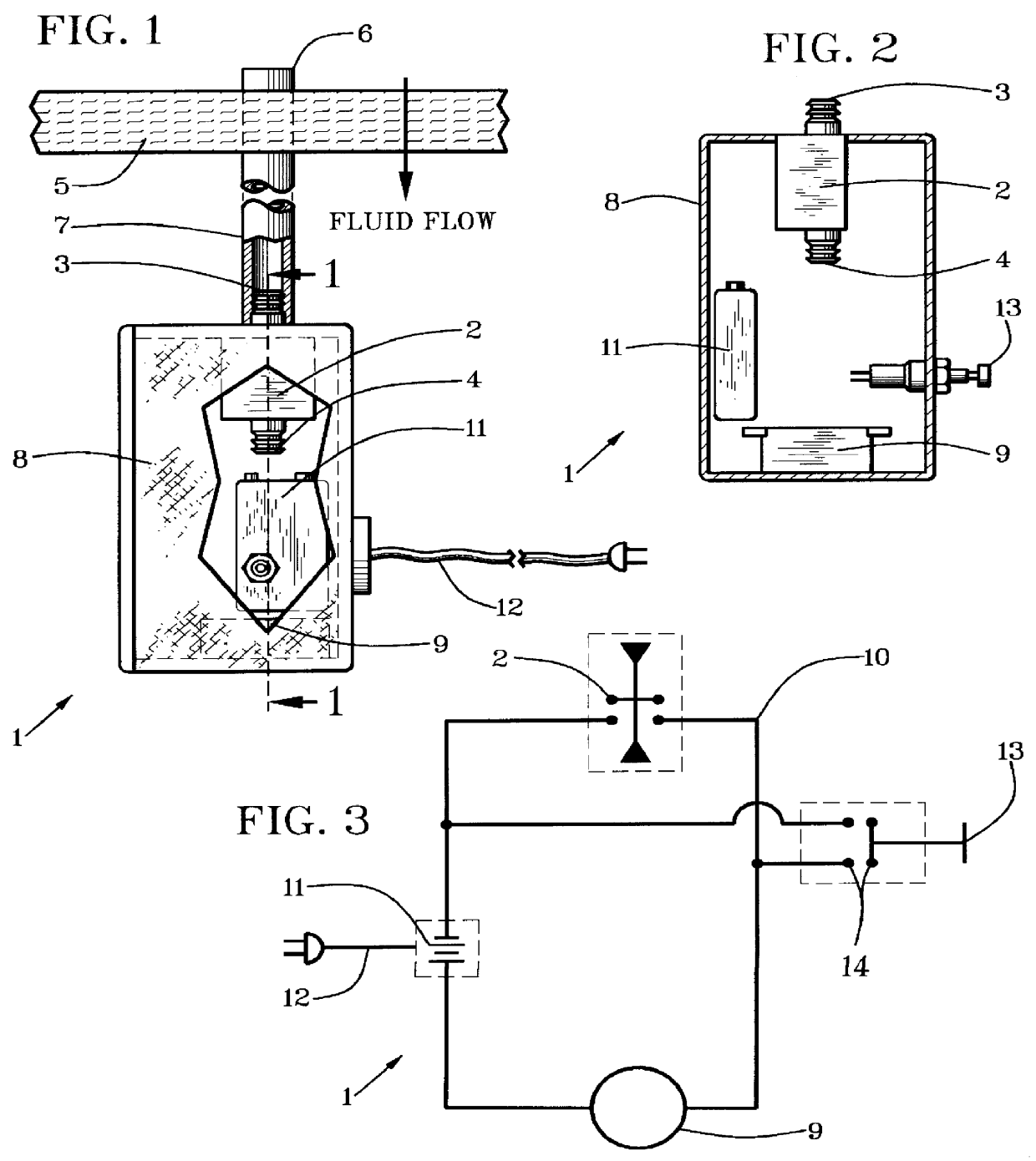
Terms used to describe features of this invention are listed below with numbering in the order of their initial use with reference to the drawings. These terms and numbers assigned to them designate the same features wherever used throughout this description.

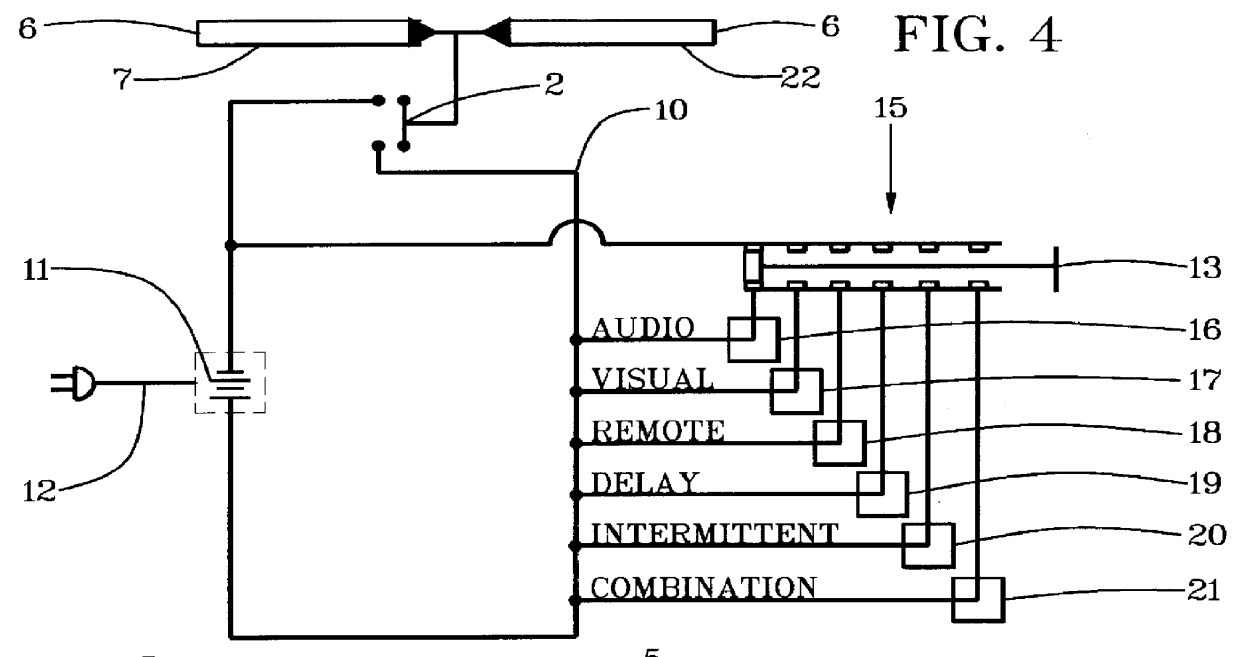
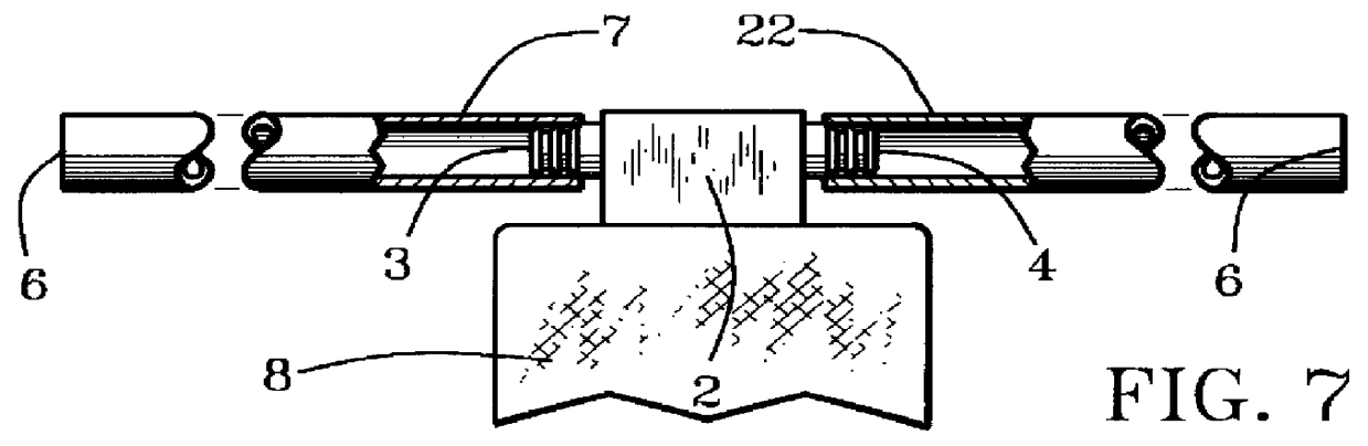
Referring first to FIGS. 1-3, a filter alert 1 has a pressure-differential switch 2 with at least one fluid-pressure inlet aperture such as a positive-pressure inlet aperture 3 and a negative-pressure or a low-pressure inlet aperture 4. For a pressure-differential switch 2 that is operated by positive pressure or a relatively high pressure in relationship to an intended filter 5, a monitored-pressure terminal 6 of a positive-pressure tube 7 is positioned in fluid communication between the positive-pressure inlet aperture 3 and a positive-pressure side of the intended filter 5.

The pressure-differential switch 2 is positioned on an alert container 8 which contains a filter-condition alert such as a buzzer 9 which is actuated throu...


PUM

PropertyMeasurementUnit
voltageaaaaaaaaaa
pressureaaaaaaaaaa
fluid-pressureaaaaaaaaaa

Abstract

A filter alert has a pressure differential switch that is responsive to positive and/or negative pressure through a pressure tube. The pressure tube is in fluid communication intermediate a positive-pressure or high-pressure side of an intended filter and a positive-pressure inlet aperture of a pressure-differential switch for indication of positive pressure across the intended filter. Optionally, the pressure tube is in fluid communication intermediate a negative-pressure or low-pressure side of a filter and a low-pressure inlet aperture of the pressure-differential switch for indication of low pressure across the filter. The pressure-differential switch actuates an actuator for alarm signals for desired action. The filter alert also includes a switch condition communication component, a filter condition alert and an alert container on which the pressure-differential switch is positioned.

Description

1. Field of the InventionThis invention relates to warning and controls in relation to filter conditions.2. Relation To Prior ArtThere are warning and control devices in relation to filter conditions but none known that communicate predetermined response to predetermined levels of either positive or negative pressure with a convenient self-powered unit in a manner taught by this invention.Examples of different but related filter warning and control systems are described in the following patent documents. U.S. Pat. No. 5,388,189, issued to Kung, described an alarm filter in an expert system for communications network that was not pressure-operated as taught by this invention. U.S. Pat. No. 5,325,809, issued to Mulle, Jr. described a hair-drier alarm that whistled with negative-pressure intake air when the filter was clogged with hair or other material and prevented negative-pressure entry of air into the hair drier except through the negative-pressure whistle. U.S. Pat. No. 5,124,957...

Claims


Application Information

Patent Timeline
Patent Type & Authority Patents(United States)
IPC IPC(8): B01D35/14B01D35/143
CPCB01D35/143
Inventor CHAMPIE, MAX C.
Owner CHAMPIE MAX C
Why Eureka
Try Eureka