Reduction gear apparatus

Inactive Publication Date: 2000-08-15
OKUBO HAGURUMA IND KK ALSO TRADING AS OKUBO GEAR CO LTD +1
View PDF17 Cites 22 Cited by
  • Summary
  • Abstract
  • Description
  • Claims
  • Application Information

AI Technical Summary

Problems solved by technology

It thus requires a large space for mounting.
The weight also becomes large, with the result that it is no longer suitable for use in a vehicle.
As a result, as shown in FIG. 1, the total length becomes large and the weight also becomes large, resulting in a higher cost.

Method used


Image

  • Reduction gear apparatus
  • Reduction gear apparatus
  • Reduction gear apparatus

Examples


Embodiment Construction

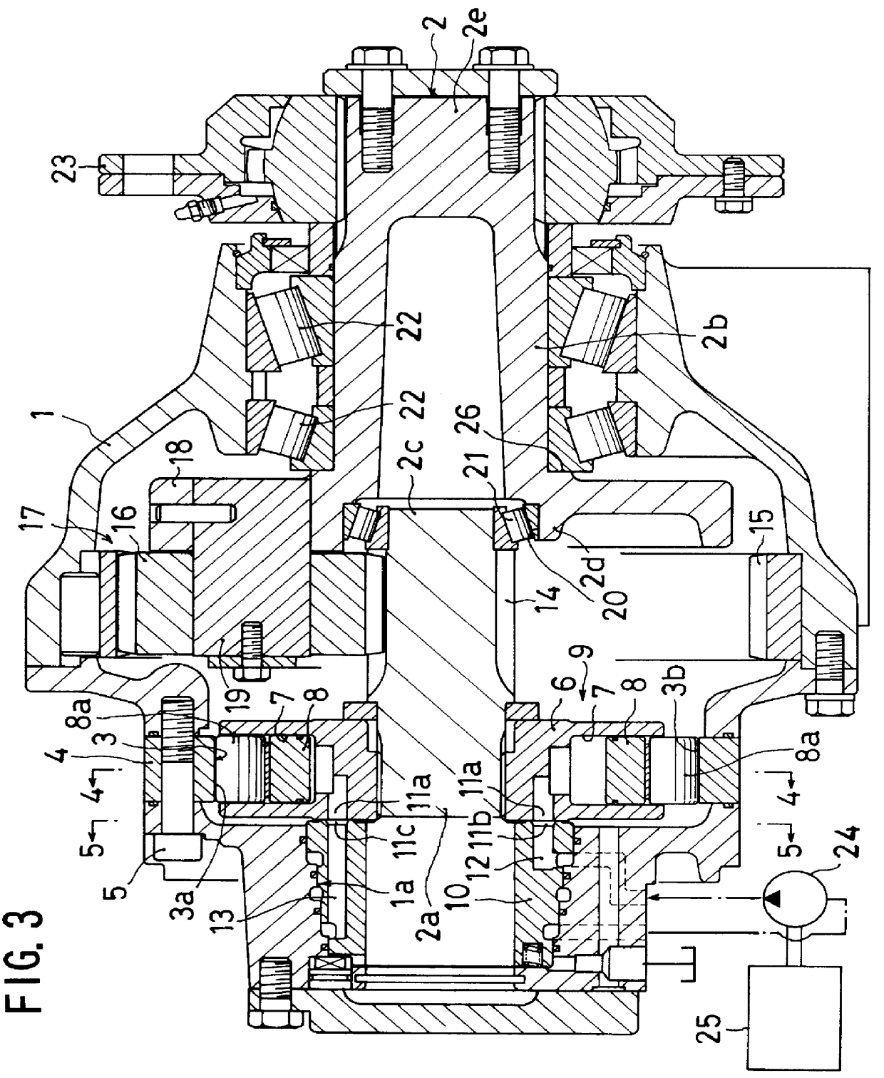
An explanation will now be made about an embodiment of the present invention with reference to the enclosed drawings. In FIG. 3 reference numeral 1 denotes a casing of a reduction gear, reference numeral 2 denotes an output shaft which is made up of a plurality of relatively rotatable rotary shafts 2a, 2b disposed on the same axial line. This output shaft 2 is arranged to extend from the inside of the casing 1 toward the outside thereof. In a manner to enclose one 2a of the output shafts 2a, 2b which constitute the output shaft 2, there is disposed a cam ring 4 so as to be fixed to the casing 1 by means of bolts 5. This cam ring 4 has on its inner circumference a cam surface 3 of a trochoidal curve which is made, as shown in FIG. 4, by alternately arranging six mountains (projections) 3a and six valleys (recesses) 3b which respectively project and recess in the diametrical direction. A cylinder block 6 is provided on the rotary shaft 2a so as to rotate therewith. The cylinder block ...


PUM


Abstract

An output shaft is constituted by a plurality of rotary shafts which are disposed on the same axial line so as to be rotatable relative to each other. A cam ring which fixedly encloses one of said rotary shafts has a cam surface with radial projections and recessions on an inner peripheral surface of the cam ring. A cylinder block which is mounted on said one of the rotary shafts has formed therein a plurality of cylinders for containing in each thereof a piston which is radially moved by sliding contact with the cam surface. A sun gear is mounted on said one of the rotary shafts. Planetary gears are mounted on remaining at least one of the rotary shafts so as to be rotatable in gearing mesh with the sun gear and an internal gear which is fixedly mounted around the sun gear.

Description

1. Field of the InventionThe present invention relates to a reduction gear apparatus (or a speed reducer) which is used for speed reduction of various machines such as a concrete mixing car, a swiveling apparatus and a travelling apparatus for a hydraulic shovel, a lifting apparatus for a carriage car (or a transporting car), or the like.2. Description of the Related ArtIn various kinds of machines, there has hitherto been practiced to reduce the rotational speed of the machine by the combination of a hydraulic motor and a toothed gear type of reduction gear, or only by a hydraulic motor. The object of using this kind of speed reducing means is to obtain a low speed and high torque. For this purpose, the following arrangement has been employed. Namely, the hydraulic pump is driven by a driving source such as an engine of the machine. The delivery fluid or discharged fluid from the hydraulic pump is supplied to a swash plate type of axial piston motor "a" as shown, e.g., in FIG. 1. T...

Claims


Application Information

Patent Timeline
IPC IPC(8): F01B3/00F16H47/04F16H47/00
CPCF01B3/00F16H47/04
Inventor KOSODO, HIROSHIOTSUKA, SATOSHI
Owner OKUBO HAGURUMA IND KK ALSO TRADING AS OKUBO GEAR CO LTD
Why Eureka
Try Eureka