When using a jig saw or scroll saw, it is often necessary to detach one or both ends of the saw blade from the saw. For example, worn or broken blades require replacement, one blade type or size may be replaced with another type or size for a specific application or during particular
cutting operations, or one end of the blade may be detached from the
machine so that the freed end may be passed through a bore in the workpiece. As such, the ease of operation of the clamping device connecting the saw blade to the saw becomes important.
Because the blade may need to be detached or replaced frequently, saw blade chucks that may be operated with little effort and that require little time in order to detach or replace saw blades provide distinct advantages. U.S. Pat. No. 5,363,733, issued to Baird et al. on Nov. 15, 1994, provides a saw blade chuck that may be quickly engaged and disengaged to secure and release an end of a saw blade. The elements of the chuck of the '733 patent are arranged so as to provide a
mechanical advantage that magnifies the force applied by the operator to engage the clamp and secure the blade within the chuck. Although the chuck of the '733 patent provides distinct advantages over the known saw blade clamping devices, it must be manually engaged and disengaged from clamping the saw blade and it also must be manually adjusted to account for saw blades having different thicknesses.
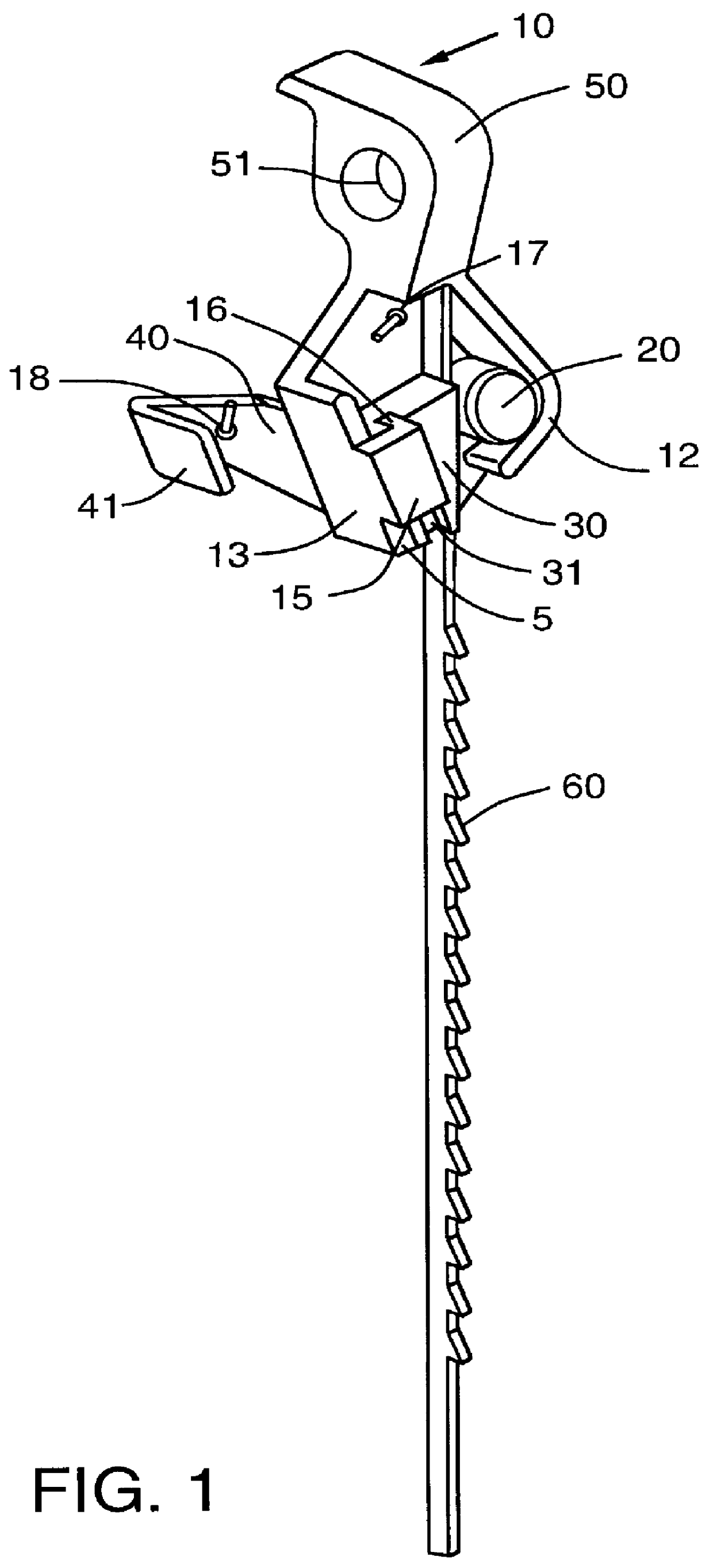
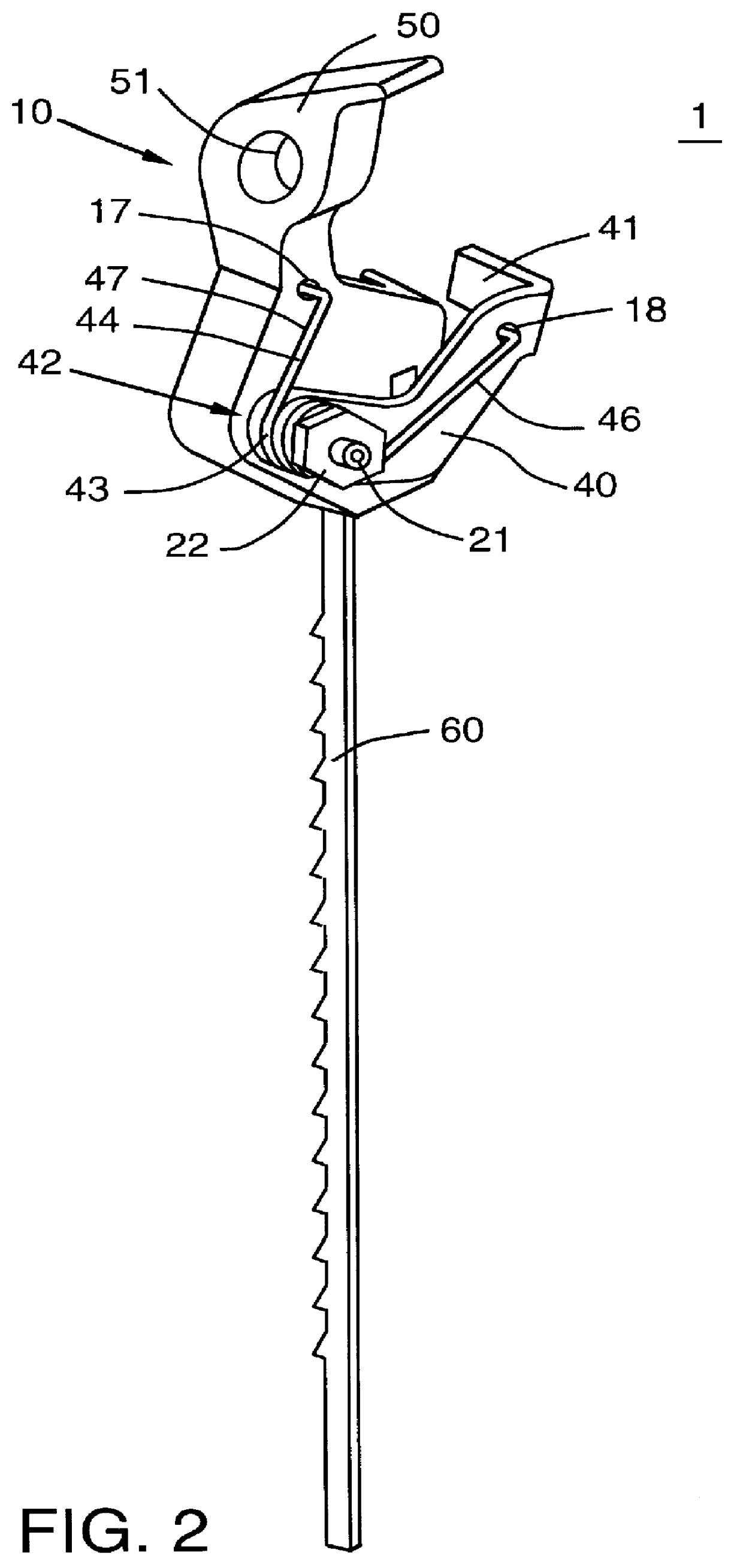
The present invention is directed, in part, to a clamping device which addresses the above-discussed needs, among others, and which, in particular, provides an apparatus for efficiently and effectively fastening a saw blade to a scroll saw and like sawing devices with the need for minimal adjustment by the operator. Moreover, it will be appreciated that the present invention may be applied to the more general task of quickly and easily clamping and holding in place an object of virtually any type so long as the structural elements of the present invention are sized to fit that object.
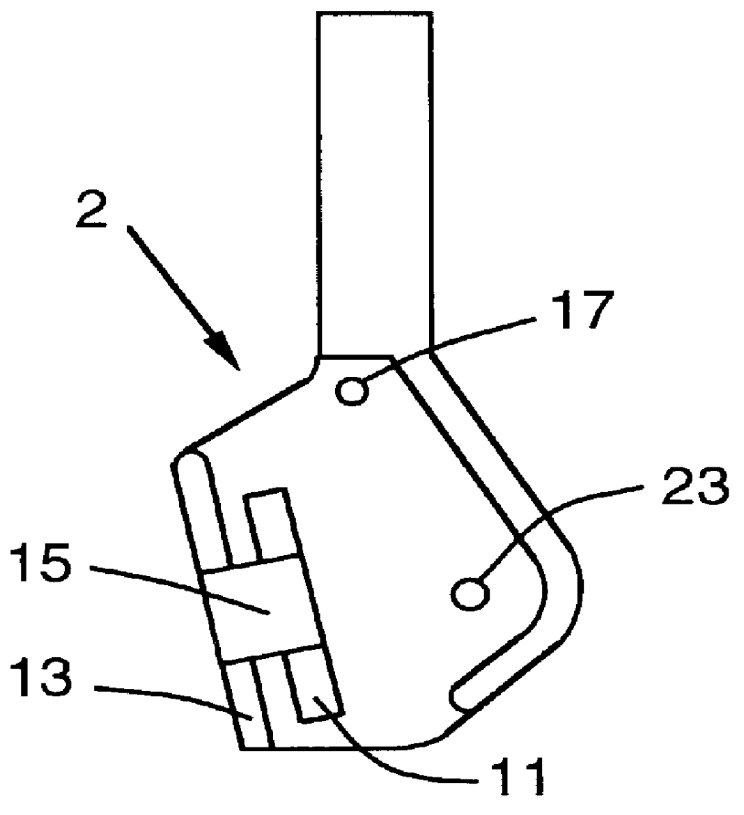
The block of the present invention may move relative to the body between a first position, wherein the block is at a first end of its range of
translational motion and at which position the clamping device is in an "engaged" configuration, and a second position, wherein the block is at a second end of its range of
translational motion and at which position the clamping device is in a "disengaged" configuration. In the clamping device's engaged configuration, a surface of the block contacts or is adjacent to the pin's perimeter. In the clamping device's disengaged configuration, the foregoing surface of the block is disposed at a distance from the perimeter of the pin that is greater than the distance between the perimeter of the pin and the surface of the block that exists when the clamping device is in the engaged configuration. Thus, as the block moves from its first position (corresponding to the device's engaged configuration), through the various intermediate positions, and to its second position (corresponding to the disengaged configuration), the distance between the surface of the block and the perimeter of the pin increases, and vice versa.
As described herein, the present invention relates to an apparatus for fastening objects including, for example, saw blades and the like, onto other devices. The present invention also is directed to scroll saws and other devices having connected thereto a clamping device having the construction of the present invention. Accordingly, the present invention provides for a clamping device that may be used to easily and quickly fasten an object such as, for example, a saw blade, to another object such as, for example, a sawing device, without the need for adjustment of the clamping device by the operator prior to use. The present device adjusts for differences in the thicknesses of clamped objects and does not require forceful manipulation by the operator in order to securely clamp the object.

