Apparatus for marinating meat products

a technology for meat products and apparatus, which is applied in grain processing, grain husking, transportation and packaging, etc., can solve the problems of reducing the effect of additives, reducing flavor, and reducing longevity

Inactive Publication Date: 2000-08-22
HORN DARRELL +1
View PDF10 Cites 70 Cited by
  • Summary
  • Abstract
  • Description
  • Claims
  • Application Information

AI Technical Summary

Problems solved by technology

In the meat processing and packing industry, the challenge has been to get the liquid additives into the meat, distribute it evenly, and then keep it in the meat during processing or packaging.
The problem has been, and remains, that over 50 percent of the liquid marinade routinely purges out of the meat during processing of the meat or after packaging.
This occurs regardless of whether the meat is cooked before packaging, and it results in a compromised effect of the additives; i.e., reduced flavor, reduced longevity, and an unattractive appearance.
Purging is particularly problematic when meat is cooked before packaging.
Even vacuum massaged products lose most of the marinade introduced into the meat during processing.
While the principle of vacuum chilling and tumbling works well in practice in the ham industry, there is no similarly effective machine available for machine marinating poultry.
For example, U.S. Pat. No. 5,564,332, described above, has insufficient heat exchange area per volume to chill certain meat products, most notably poultry, quickly enough for efficient processing.
Because poultry massaging lasts only 20 to 25 minutes, there is not enough time for sufficient heat transfer to take place to reduce the temperature of the poultry product and thereby stabilize liquid marinade in the meat matrix.
As a result, product is chilled at an extremely rapid rate.

Method used


Image

  • Apparatus for marinating meat products
  • Apparatus for marinating meat products

Examples


Embodiment Construction

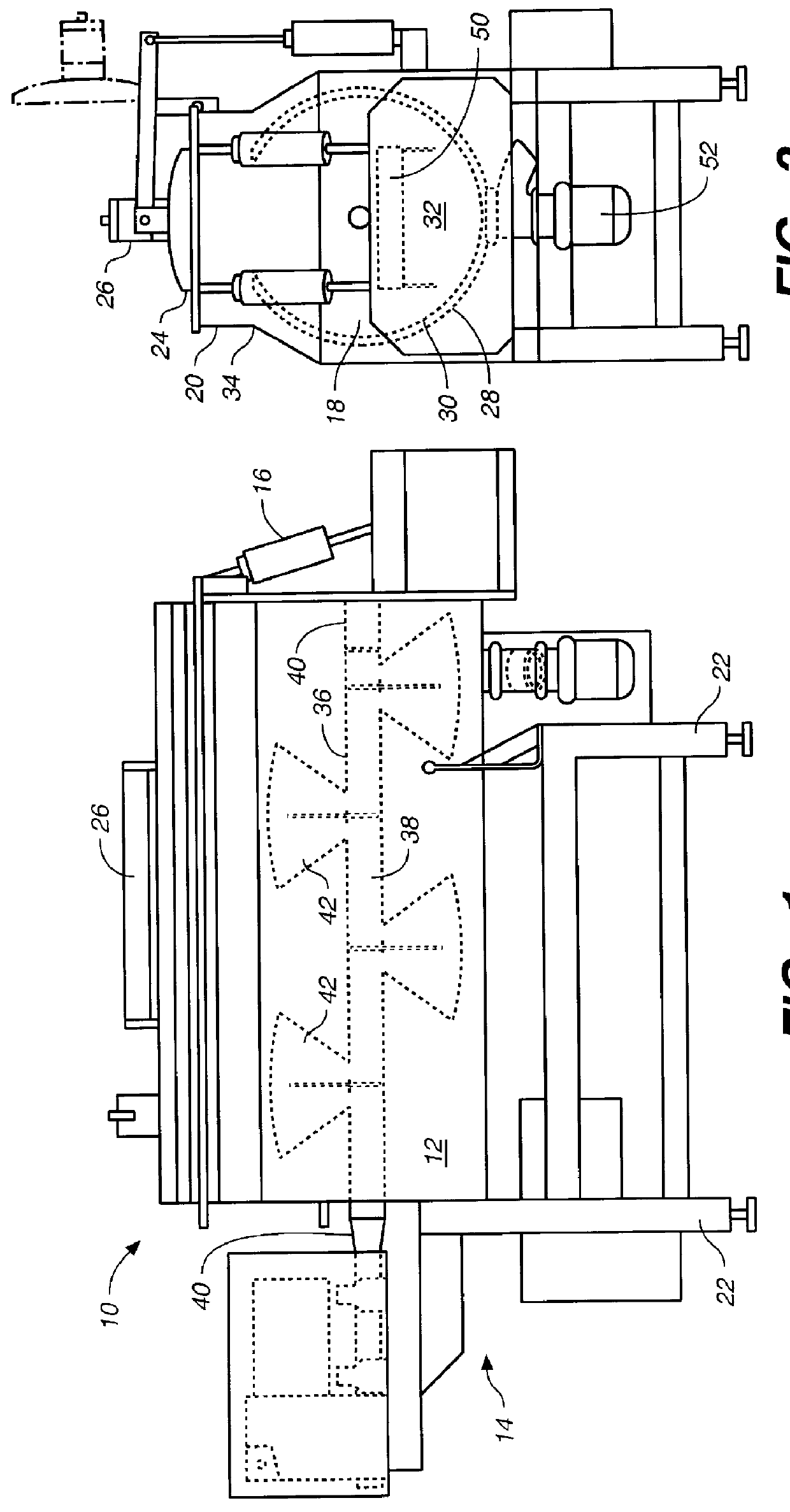
As shown in FIGS. 1 and 2, the meat marinating machine of the present invention, generally denominated 10, comprises a generally horizontal vessel 12 having a first end 14 and a second, discharge end 16, a substantially cylindrical inferior portion 18 and a substantially cuboid superior portion 20, thereby giving a keyhole profile when viewed on end (see FIG. 2). The vessel is supported on a base or frame structure 22. A rectangular opening 24 runs the entire length of the superior portion of the vessel for rapid loading, the opening covered by a motorized sealed vacuum cover 26 when in operation.

The outer wall 28 of the cylindrical portion of the vessel comprises a hollow jacket 30, through which refrigerant may be circulated during operation. Preferably the jacket has a baffling system (not shown) for control of the flow of refrigerated liquid. In operation, the interior chamber of the vessel 32 is filled no higher than the upper border 34 of the cylindrical portion of the vessel,...


PUM


Abstract

A vacuum meat marinating machine for products requiring a short vacuum massage cycle, comprising a substantially horizontal cylindrical vessel having a large opening at the top for rapid loading of product, said opening covered by a sealed vacuum cover during operation, and further having a hollow outer wall comprising a jacket for the circulation of liquid refrigerant. A paddle agitator is located within the vessel, having a hollow shaft running longitudinally within the vessel. Affixed at an angle to the shaft are a plurality of hollow triangular-shaped paddles, which paddles push product horizontally during operation. Liquid refrigerant circulates through the hollow wall of the vessel, as well as the hollow agitator shaft and paddles. The agitator shaft is connected to a reversible motor that periodically reverses the direction of rotation, thereby maximizing heat exchange between product and liquid refrigerant.

Description

1. Field of the InventionThis invention relates to meat marinating machines, and more particularly to a refrigerated cylindrical drum paddle-agitator mixer operated under a vacuum.2. Description of the Prior ArtMethods and devices for marinating meat are many and varied. Early methods of deep marination include the injection of liquid via syringe. Advances over this method included the technique of massaging (or tumbling) meat under vacuum while exposing it to liquid marinade. In a vacuum, meat expands significantly and air may be extracted; the marinade then fills the interstices of the tissue in the hope that it will largely remain in place after the product is restored to normal atmospheric pressure. For larger pieces of meat, a combination of injection and vacuum massaging may be used for even distribution of the marinade.Ordinarily, liquid marinades for meat are water based and contain additives to produce one or more results, including tenderizing, preserving, macerating, and / ...

Claims


Application Information

Patent Timeline
Patent Type & Authority Patents(United States)
IPC IPC(8): A23B4/26A23L1/318A23L3/015B01F15/06B01F15/00B01F7/00A23L13/70B01F7/02
CPCA23B4/26A23L1/318A23L3/0155B01F15/00954B01F15/065B01F15/068B01F7/0025B01F7/02A23L13/70B01F27/112B01F27/60B01F35/181B01F35/95B01F35/92
Inventor HORN, DARRELLLENNOX, JOHN
Owner HORN DARRELL
Why Eureka
Try Eureka