

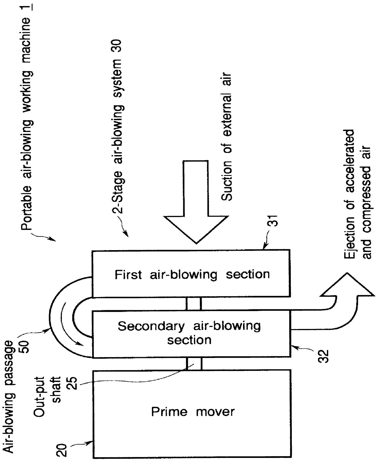
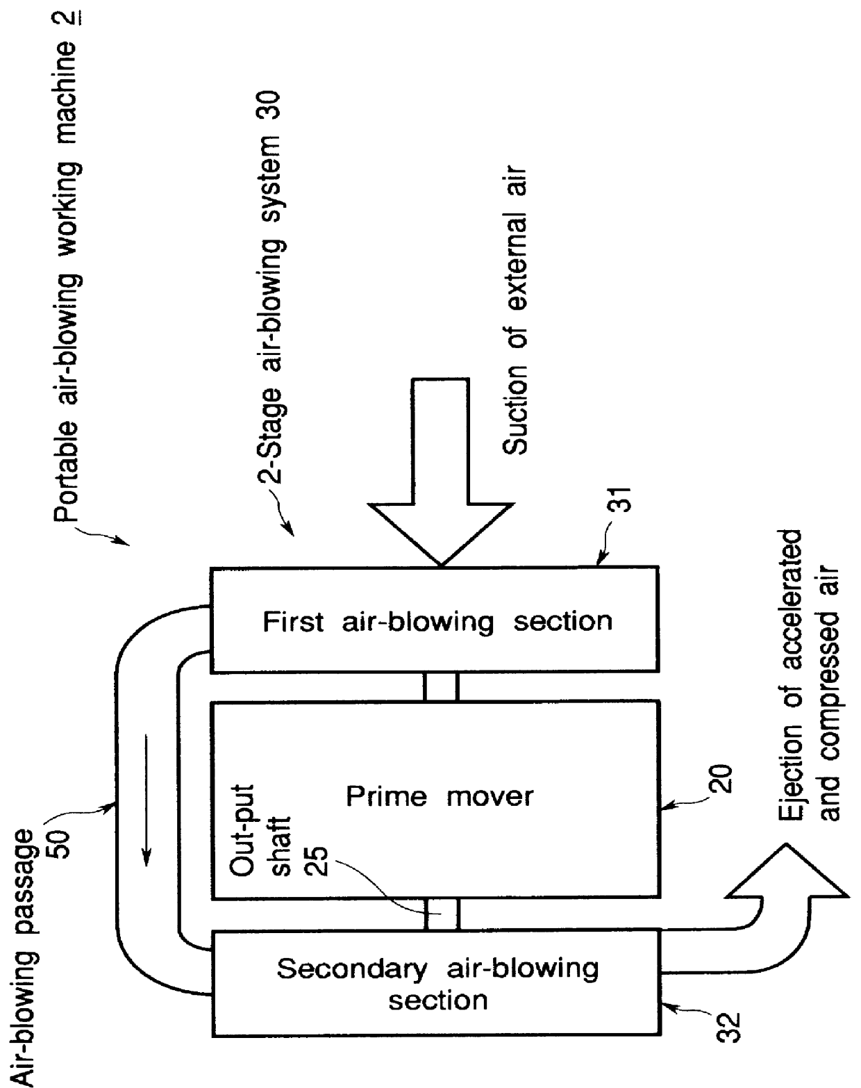
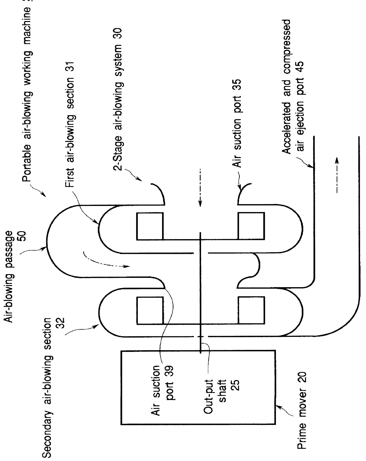
Portable air-blowing working machine
a working machine and portable technology, applied in the direction of machines/engines, cleaning equipment, and turbine growth, can solve the problems of reducing the noise output of the portable air-blowing working machine, reducing the noise pollution of the air-blowing cleaner, and reducing the noise output. , to achieve the effect of reducing the noise pollution, and reducing the noise outpu
- Summary
- Abstract
- Description
- Claims
- Application Information
AI Technical Summary
Benefits of technology
Problems solved by technology
Method used
Image

Examples
case 33
The volute case 33 of the first air-blowing section 31 and the volute case 34 of the secondary air-blowing section 32 are provided at the center of the axially outward surfaces thereof with the circular air-intake ports 35 and 39, respectively, the center of the air intake ports 35 and 39 being coaxial with the axis of the crank shaft 25. At the outer circumferential portions thereof, the volute cases 33 and 34 define volute chambers 33A and 34A, respectively. A pair of plate portions 33b and 34b constituting the rear faces of the outer circumferential portions of the volute chambers 33A and 34A, respectively, are contacted with each other to form a partition wall. The inner circumferential end portions 33c and 34c of the partition wall plates 33b and 34b are bent axially away from each other, thereby forming a U-shaped groove 48. The outer peripheral portion 43a of the main plate 43 of the double fan 40 is radially extended beyond the peripheries of the fan blades 41 and 42, such t...
PUM
 Abstract
Description
Claims
Application Information