Submerged pipeline manifold for offloading mooring buoy and method of installation

a pipeline and manifold technology, applied in the field of floating offloading and storage facilities, can solve the problems of difficult to tow the pipe to the mooring buoy, large load lifting,

Inactive Publication Date: 2000-08-29
FMC TECH INC
View PDF10 Cites 33 Cited by
  • Summary
  • Abstract
  • Description
  • Claims
  • Application Information

AI Technical Summary

Problems solved by technology

The installation of such metal pipe on the offloading mooring buoy requires the lifting of large loads because of the weight of the pipe.
Furthermore, it has been difficult to tow th...

Method used


Image

  • Submerged pipeline manifold for offloading mooring buoy and method of installation
  • Submerged pipeline manifold for offloading mooring buoy and method of installation
  • Submerged pipeline manifold for offloading mooring buoy and method of installation

Examples


Embodiment Construction

Embodiment of FIGS. 1-3

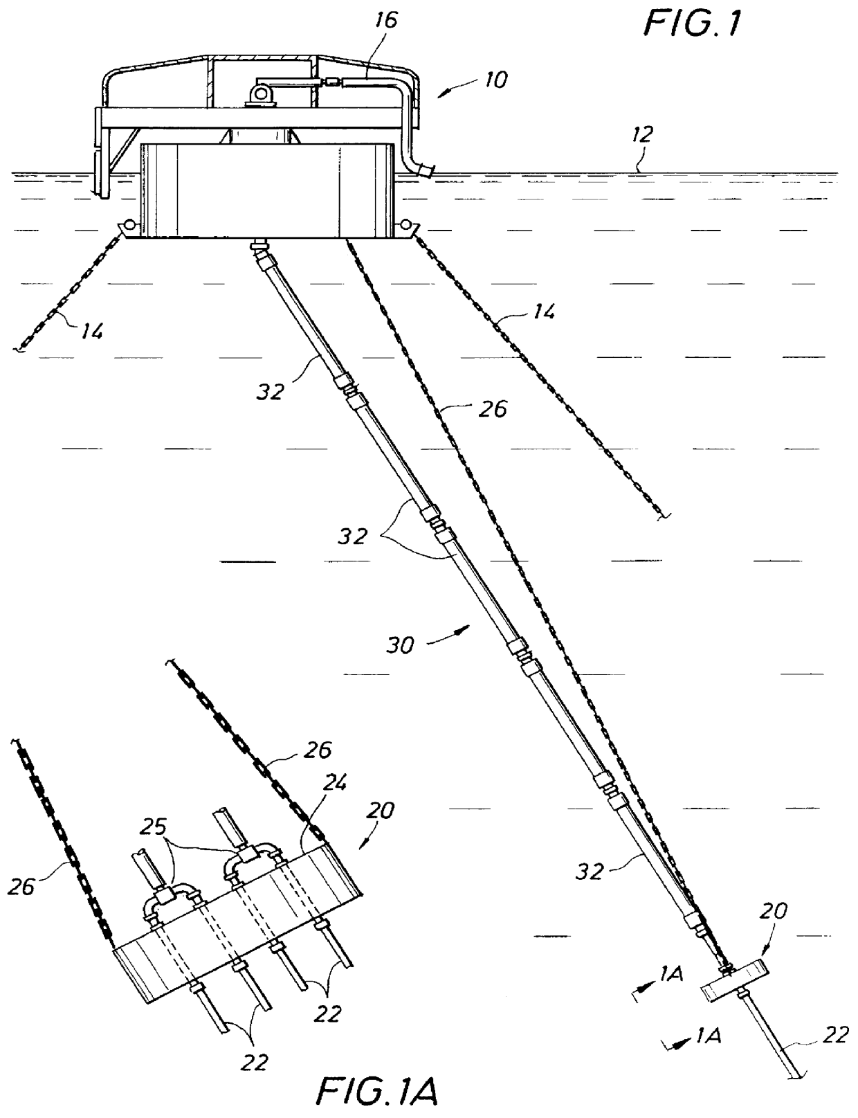
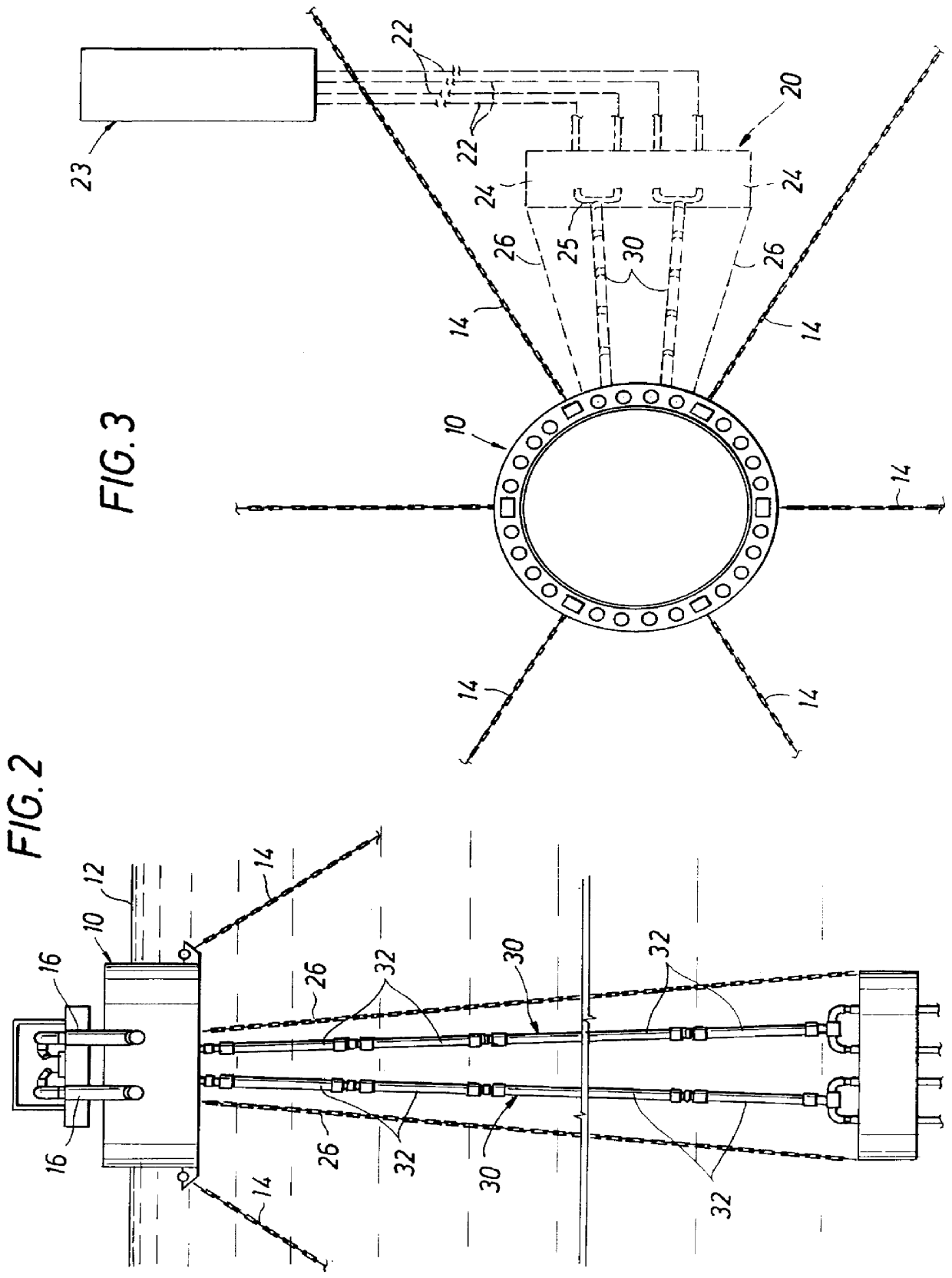
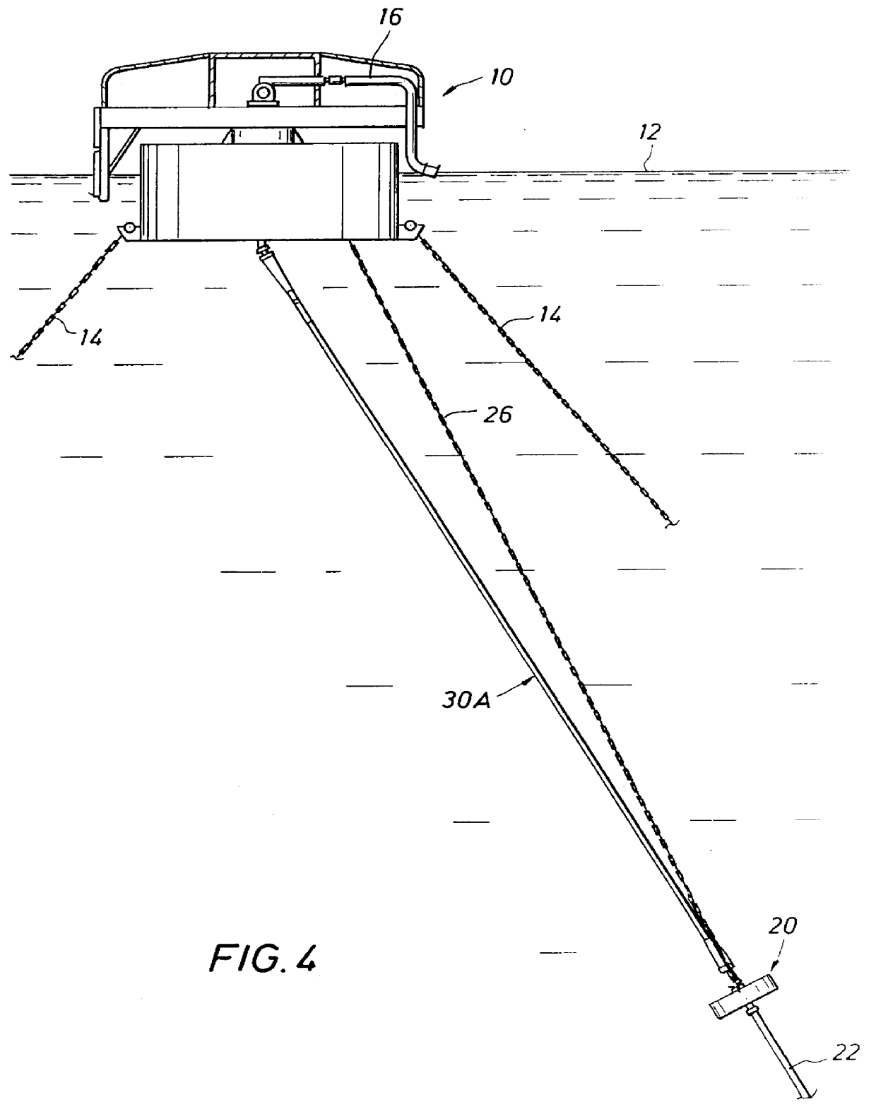
Referring to the embodiment of FIGS. 1-3, a catenary anchor leg mooring (CALM) buoy is shown generally at 10 floating on the sea surface 12 and having a plurality of anchor legs 14 extending in a catenary to the sea floor and anchored thereto. Suitable product lines 16 extend from the top of buoy 10 and are adapted for connection to a product transport vessel (not shown), such as a shuttle tanker, to supply product thereto.

A submerged pipeline end manifold (SPLEM) is shown generally at 20 and has a plurality of steel product flowlines 22 connected thereto which extend from a permanent production storage facility, such as a permanently anchored storage vessel or tanker shown schematically at 23 in FIG. 3. Such storage facility may be a bottom supported facility rather than a vessel. Suitable valves and manifolds 25 for product flowlines 22 are provided to control the product flow to mooring buoy 10 and to permit recirculation back to the permanent storage facil...


PUM


Abstract

In certain offshore locations, for example off the West Coast of Africa, FPSO facilities provide an offloading facility to receive and load produced crude oil onto shuttle tankers. In such arrangements FPSO facilities use spread moored tankers with flowlines suspended in the water column to an offloading buoy or buoys which are located 1,000 to 1,500 meters away from the FPSO. Typically steel pipe flowlines as used with intermediate floatation to provide a suitable configuration that will avoid detrimental loads being imposed resulting from relative motions of the FPSO and the offloading buoy. According to the invention, a Suspended Pipe Line End Manifold (SPLEM) is connected to the end of the flowline assembly for support during towout. The SPLEM is positioned near the buoy and then connected at the sea surface to the bottom of the buoy by flexible leads such as anchor chains. The SPLEM is then flooded by selectively flooding compartments to cause it to sink to an operational position below the buoy. Next, additional submarine hoses or flexible pipe are connected to complete the flowline to the buoy.

Description

1. Field of the InventionThis invention relates generally to floating offloading and storage facilities for subsea hydrocarbon products, and more particularly to such offloading and storage facilities utilizing an offloading mooring buoy.2. Description of the Prior ArtOffloading mooring buoys for shuttle tankers or other vessels have been used with floating production storage and offloading facilities, such as permanently moored storage tankers. Normally, the storage and offloading facility is connected directly to subsea product lines and receives product from subsea wells. In some locations, dependent on the various water depths and distances, an offloading mooring buoy may be located one thousand (1,000) to fifteen hundred (1,500) meters from a permanent floating storage facility. Shuttle tankers connect to the offloading mooring buoy to receive product therefrom for transportProduct flowlines or risers normally extend from the subsea wells to the permanent floating storage facil...

Claims


Application Information

Patent Timeline
IPC IPC(8): B63B22/00B63B22/02E21B17/01E21B17/00
CPCB63B22/021E21B17/015B63B2035/4486
Inventor KELM, RON L.ETHERIDGE, CHARLES O.LIU, YONGHUI H.MCCOLLUM, JERRY L.
Owner FMC TECH INC
Why Eureka
Try Eureka