Chamber with drier

a technology of chambers and dryers, applied in the direction of lighting and heating apparatus, heating types, separation processes, etc., can solve the problem of poorly utilized desiccant granulates

Inactive Publication Date: 2000-08-29
THES INVESTMENTS LLC
View PDF26 Cites 18 Cited by
  • Summary
  • Abstract
  • Description
  • Claims
  • Application Information

AI Technical Summary

Benefits of technology

Advantageously, the antechamber filled with desiccant granulates comprises filters at both ends of its baffle, these filters holding the desiccant granulates in the baffle and preventing the spread of dust coming from the erosion of the granulates.

Problems solved by technology

These drawbacks include especially the fact that the drier must be mounted first of all on the orifice of the to chamber and replaced from time to time in order to regenerate its granulates and the fact that, on these occasions, the chamber is in direct communication through its aperture with the outside environment.
It furthermore proves to be the case that the desiccant granulates are poorly utilized when they are simply heaped into an antechamber placed before the aperture of a dryer chamber, for the circulation of air follows preferred paths leading to an inhomogeneous saturation in moisture of the granulates.

Method used


Image

  • Chamber with drier
  • Chamber with drier
  • Chamber with drier

Examples


Embodiment Construction

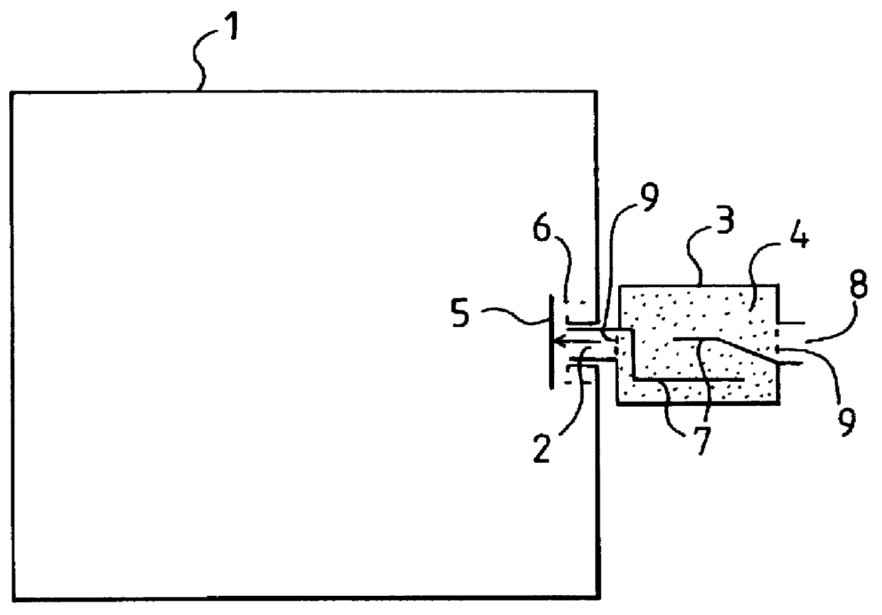
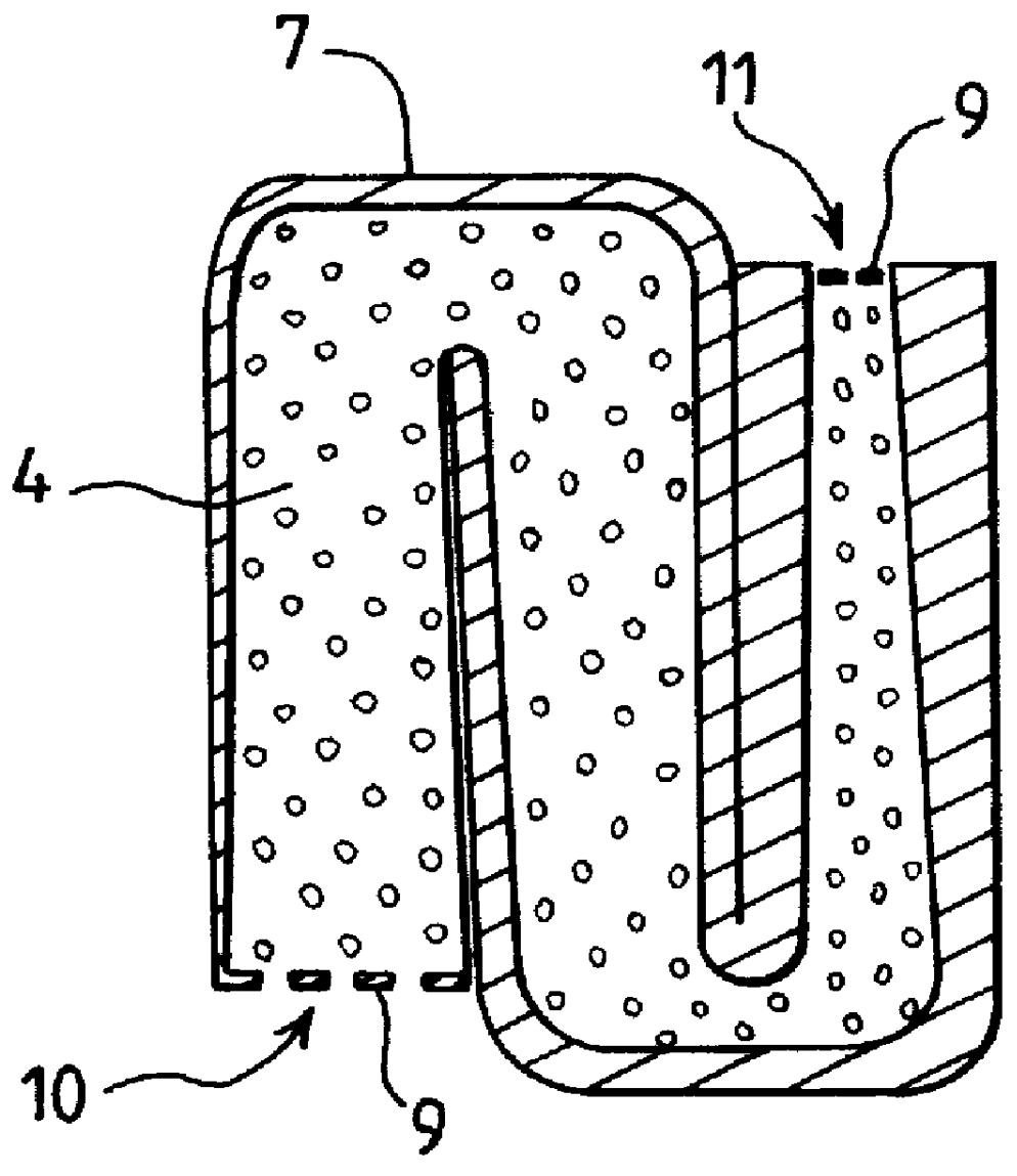
FIG. 1 shows a clean chamber 1 communicating with the outside environment through an orifice 2 in order to prevent a pressure differential, between its internal volume and the outside environment, that could make it implode or explode. This clean chamber 1 is liable to exchange a flow of air with the outside environment under the effects of the pressure variations of this outside environment. To prevent this exchange of air flow from leading to a contamination of the internal volume of the clean chamber by moist air that could lower the dew point threshold beyond at which water vapor starts getting condensed and to prevent disturbances such as crystals or condensation in the path of an optical beam travelling through the internal volume of the clean chamber 1, it is necessary to dehumidify the incoming air flow. This is obtained in a known way by making this air flow go through an antechamber 3 in which it is brought into contact with desiccant granulates 4 such as granulates known ...


PUM


Abstract

A chamber with drier comprises a clean chamber communicating with the outside environment through an orifice equipped with a detachable antechamber filled with desiccant granulates. The chamber comprises, between the orifice of the clean chamber and the detachable antechamber filled with desiccant granulates, a valve that is closed at rest and opened by the positioning, on the orifice of the clean chamber, of the antechamber filled with desiccant granulates and the antechamber filled with desiccant granulates contains a baffle that prevents the air from following a direct route and forces it to encounter the majority of the desiccant granulates. Advantageously, the baffle is convergent and there electronic monitoring of the moisture saturation of the desiccant granulates. Furthermore, there may be a single-effect back flow valve bypassing the baffle for a fast decompression of the clean chamber.

Description

1. Field of the InventionThe present invention relates to the dehumidification of a chamber communicating with an variable-pressure outside environment in order to keep it below a certain dew point threshold to prevent the appearance of crystals or condensation under normal conditions of use. It is indeed important in certain chambers communicating with variable-pressure outside environments, especially chambers enclosing optical projection systems, to prevent the appearance of crystals or condensation vapor that might disturb the propagation of light rays.2. Description of the Prior ArtTo do so, there are known ways of mounting a drier on the orifice through which a chamber communicates with the outside environment. This drier consists of an antechamber open on to the outside environment and filled with desiccant granulates. Thus, the air that the chamber takes from the outer environment as a result of pressure variations gets dried before it reaches the interior of this chamber.In...

Claims


Application Information

Patent Timeline
Patent Type & Authority Patents(United States)
IPC IPC(8): G06F15/80G06F15/76B01D53/26F16K15/02F24F3/14F26B5/16F26B21/00F26B25/16
CPCF24F3/1411G06F15/8007G06F15/8023F24F2003/144
Inventor GUIRAGOSSIAN, NICOLAS
Owner THES INVESTMENTS LLC
Why Eureka
Try Eureka