Crossing guard

a cross-border guard and cross-window technology, applied in the direction of traffic gates, ways, constructions, etc., can solve the problems of ineffective devices, impracticality of using stronger materials such as steel, passengers being injured, etc., to achieve the effect of safe and effective restraint of vehicles

Inactive Publication Date: 2000-09-12
QUIXOTE
View PDF14 Cites 23 Cited by
  • Summary
  • Abstract
  • Description
  • Claims
  • Application Information

AI Technical Summary

Benefits of technology

With these considerations in mind, it is therefore an object of this invention to provide a crossing guard that safely and effectively restrains vehicles which impact the crossing guard.
It is a further object of this invention to provide a crossing guard that will prevent vehicles from passing through the crossing guard when it is in the down position.
It is a further object of this invention to provide a crossing guard that will act as a barrier and absorb the energy of a vehicle while at the same time preventing injury to the passengers of the vehicle.

Problems solved by technology

While practical, these devices can be ineffective because many motorists simply drive around or through the arm.
Use of stronger materials such as steel can be impractical because of the added weight and the concerns about the safety of drivers who crash into the arm.
While the prior art discloses means for stopping vehicles, the prior art devices have several drawbacks.
First, because the cables are not joined together, the upper cable(s) can ride up and over the hood of a vehicle and cut through the roof, thereby injuring the passengers.
Second, Hirsh does not disclose additional energy absorbing material that will aid in stopping the vehicle before the cables begin restraining the vehicle.
Third, none of the prior art devices discloses the use of ties to hold the cables in position relative to one another so that the cables remain somewhat in position relative to each other.
Finally, the prior art fails to disclose the locking mechanisms used herein to lock the arm and cable ends in place.

Method used


Image

  • Crossing guard
  • Crossing guard
  • Crossing guard

Examples


Embodiment Construction

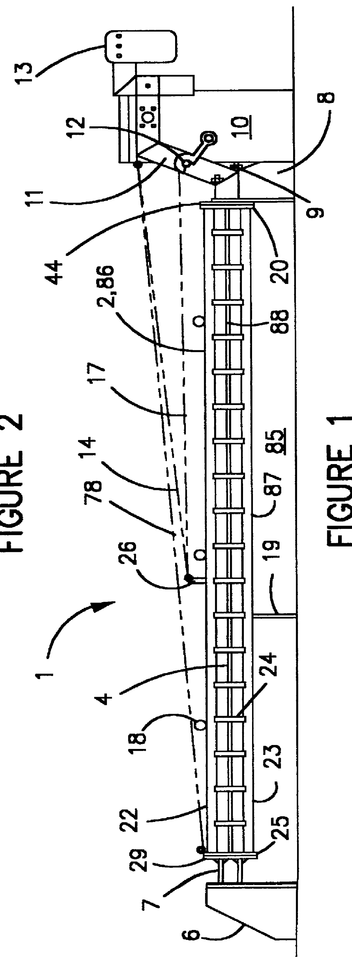
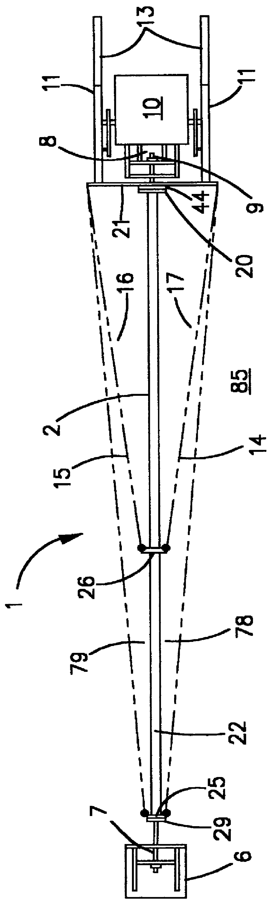
As shown in FIGS. 1 and 2, the crossing guard 1 generally comprises an operator 10 mounted on one side of a thoroughfare 85, the operator 10 having two arms 11 attached thereto. Crossing guard 1 is preferably positioned approximately twenty feet from the bridge opening or railroad track, although this distance can vary depending on the width and geometry of the bridge opening or railroad track. A gate 2 is attached to arms 11. Counterweights 13 allow arms 11 and gate 2 to rise and fall without the need for a very powerful operator motor. Operator 10 includes an arm lock 12 to hold arms 11 in place should gate 2 be sheared away at impact. In a preferred embodiment, counterweights 13 are of sufficient weight so that a one horsepower motor can raise and lower the gate 2.

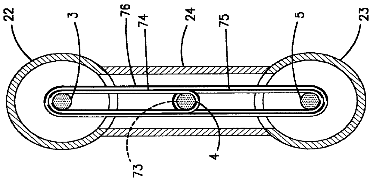
Gate 2 comprises a support 86 which supports a plurality cables. Preferably, support 86 comprises a pair of gate members 22, 23 which are preferably hollow. Gate members 22, 23 are held apart vertically by a series of s...


PUM


Abstract

A crossing guard is disclosed which comprises an operator positioned on one side of a thoroughfare for raising and lowering an arm, a gate connected to the arm, a first lock positioned on the opposite side of the thoroughfare, a plurality of cables supported within the gate, joined together at fixed points intermediate the ends of the cables, and a first end assembly connectable with the cables and the gate at the end of the gate opposite the operator with the first end assembly engagable with the first lock. The device further comprises a second lock positioned on the side of the thoroughfare nearer said operator engagable with a second end assembly positioned on the end of the gate nearer said operator.

Description

1. Field of the InventionThis invention relates to thoroughfare crossing guards, more particularly to a crossing guard for use at bridge and railroad crossings.2. Prior ArtMany devices have been used to prevent motorists on a thoroughfare from crossing railroad tracks or even raised bridges. Many of these devices included a cross arm connected to an operator that raises and lowers the arm. While practical, these devices can be ineffective because many motorists simply drive around or through the arm. If a motorist is not paying attention he can simply drive through the arm and into the way of an oncoming train or other danger because the arms are constructed from wood or plastic. Use of stronger materials such as steel can be impractical because of the added weight and the concerns about the safety of drivers who crash into the arm.In the past, attempts have been made to use arms having cables attached thereto or cables positioned within a hollow arm member extending between the sid...

Claims


Application Information

Patent Timeline
Patent Type & Authority Patents(United States)
IPC IPC(8): E01F13/00E01F13/06E01F13/12
CPCE01F13/06E01F13/12B61L29/04
Inventor ALLARDYCE, DAVIDKNIGHT, DAVID L.
Owner QUIXOTE
Why Eureka
Try Eureka