Power-on-reset circuit providing protection against power supply interruptions

a technology of power-on-reset circuit and power supply interruption, which is applied in the direction of electric pulse generator, pulse automatic control, liquid/fluent solid measurement, etc., and can solve the problem of insufficient reliability of the integrated circui

Inactive Publication Date: 2000-09-12
STMICROELECTRONICS SRL
View PDF13 Cites 48 Cited by
  • Summary
  • Abstract
  • Description
  • Claims
  • Application Information

AI Technical Summary

Problems solved by technology

It has been observed that, in certain cases, the reliability of the integrated circuit remains insufficient.

Method used


Image

  • Power-on-reset circuit providing protection against power supply interruptions
  • Power-on-reset circuit providing protection against power supply interruptions
  • Power-on-reset circuit providing protection against power supply interruptions

Examples


Embodiment Construction

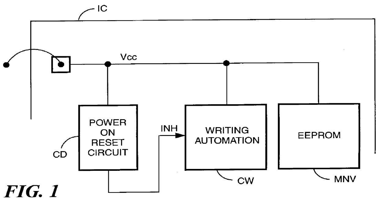
The power-on-reset circuit CD, which can also be called a temporary inhibition circuit, is also known as a starting circuit. It forms part of an integrated circuit IC, for example a memory card circuit comprising an EEPROM type memory MNV.

The memory can be written in or erased by means of a writing automaton CW. The memory must be protected against the writing of erroneous information, especially when the supply voltage is too low, and above all if the memory is organized in words of several bits. The power-on-reset circuit gives an inhibition signal INH that is applied to an inhibition input of the circuit CW to prohibit its operation in this case.

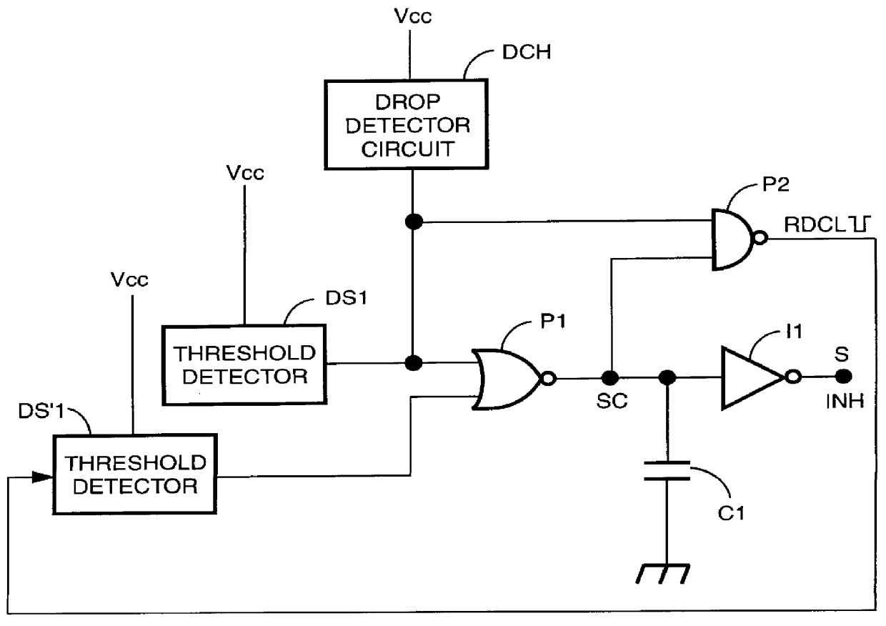
A simplified diagram of the power-on-reset circuit according to the invention is shown in FIG. 2.

The power-on-reset circuit has two circuits DS1 and DS'1 for the detection of the exceeding of a voltage threshold VS1. VS1 may be typically have a value of 3 volts to 3.3 volts, for a nominal supply Vcc0 of 5 volts.

Each of these circuits DS1 ...


PUM


Abstract

The disclosure relates to integrated circuits and, more particularly, to a power-on-reset circuit. The proposed circuit produces an inhibition signal when the power is turned on, this signal being interrupted after the supply voltage Vcc has reached a first threshold (VS1) (VS1). Furthermore, the circuit has means to re-trigger the inhibition signal when the supply voltage drops by a certain value, in doing so even if the supply voltage remains above the first threshold. The reliability of the integrated circuit is improved. The disclosed circuit is particularly applicable to the inhibition of the writing circuit of an EEPROM memory.

Description

1. Field of the InventionThe invention relates to integrated circuits and more specifically to a starting circuit or power-on-reset circuit that can be used for the temporary inhibition of certain functions of the integrated circuit when the power is being turned on. Indeed, in certain logic circuits, erroneous operations may be caused by the insufficiency of the power supply. To prevent these erroneous operations, it is preferred to totally inhibit certain functions of the integrated circuit while the power is being turned on.A power-on-reset circuit is used for this purpose. This circuit produces a signal that starts when the power is turned on and continues until the supply voltage has reached a sufficient value. This square-wave signal is applied to an input for the inhibition of each of the circuits whose operation has to be inhibited temporarily.Typically, for a nominal supply voltage of five volts, steps are taken to produce an inhibition signal that starts when the power is ...

Claims


Application Information

Patent Timeline
Patent Type & Authority Patents(United States)
IPC IPC(8): G06F1/30G06F1/24G06F1/26G01R19/165G06F1/28G11C11/413G11C16/06G11C17/00H03K17/22
CPCG01R19/16538G06F1/24G06F1/28G06F1/305H03K17/22H03K17/223
Inventor GUEDJ, MARC
Owner STMICROELECTRONICS SRL
Why Eureka
Try Eureka