Taps and containers for dispensing fluid

a technology for dispensing containers and taps, which is applied in the direction of liquid dispensing, liquid flow controllers, packaging, etc., can solve the problems of unnecessary cost of tubular seal members of these two patents, unduly complicated taps, valves and spigots for use in the consumer market, and the associated structure to house and retain tubular seal members may be more expensive than is desired

Inactive Publication Date: 2000-10-31
SCHOLLE CORP
View PDF2 Cites 56 Cited by
  • Summary
  • Abstract
  • Description
  • Claims
  • Application Information

AI Technical Summary

Problems solved by technology

One of the drawbacks of this type of tap is that the fluid is dispensed forwardly and downwardly from the front of the tap, immediately below the tab, rather than straight downwardly, directly below the tap.
Conventional taps, valves, and spigots for use in the consumer market may be unduly complicated, such as those disclosed in U.S. Pat. No. 4,621,750 to Roethel and U.S. Pat. No. 4,927,061 to Leigh et al.
Accordingly, the tubular seal members of these two patents may present unnecessary costs.
Also, the associated structure to house and retain the tubular seal member may be more expensive than is desired.

Method used


Image

  • Taps and containers for dispensing fluid
  • Taps and containers for dispensing fluid
  • Taps and containers for dispensing fluid

Examples


Embodiment Construction

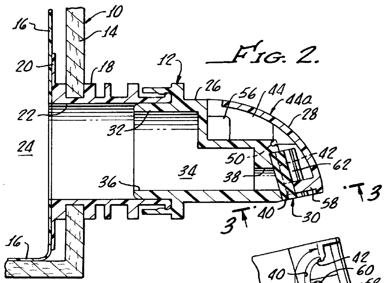
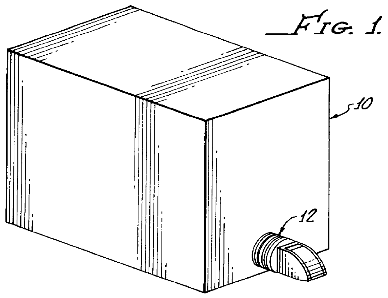
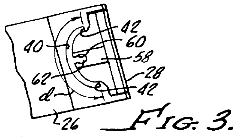
Referring to the drawings in more detail, an exemplary bag-in-box container 10 for holding a liquid, such as wine, and an exemplary tap 12 for controllably dispensing the liquid from the container 10, are both illustrated in FIG. 1. With additional reference to FIG. 2, the container 10 includes an outer shape-retaining support structure or box 14 and an inner flexible bag 16. The box 14 may be made of, for example, corrugated paper board, and the bag 16 is made from a substantially liquid-impervious material, such as from plastic sheet. As is shown in FIG. 2, the container 10 also includes a coupler 18, preferably fabricated of a pliable but substantially shape-retaining polymer material. The coupler 18, which is shown as a female coupling part in this embodiment, is preferably substantially tubular in configuration and has a flange 20 disposed at an inner end thereof. The flange 20 is sealingly attached to the bag 16 at an opening 22 of the bag. For example, the flange 20 may be he...


PUM


Abstract

A tap for dispensing fluid from a vessel includes a main tap body, an actuator, and a seal member. The main tap body includes a passage with an inlet and an outlet and a seat with a shoulder formed around the outlet. The actuator has a handled and is pivotally attached to the main tap body and dispenses fluid from the vessel upon activation of the handle by a user. The seal member is received within the seat and attached to the actuator. The seal member includes a retaining portion received against the shoulder of the seat and a sealing portion which is releasably engageable with the seat. The seal member is resilient to provide a bias force to urge the sealing portion against the seat. The actuator is pivotal between a closed position in which the sealing portion is biased against the seat, thereby preventing fluid from passing through the outlet, and an opened position in which at least a portion of the sealing portion is pulled away from the seat against the bias force, thereby allowing fluid to flow through the outlet.

Description

1. Field of the InventionThe present invention relates to a tap (i.e., a tap, valve, or spigot) for dispensing fluids and liquids. More particularly, the present invention relates to a tap used for dispensing liquid from a vessel or container. The present inventive tap may be used to dispense a fluid such as a beverage (e.g., wine) from a box-like vessel in which the beverage is packaged.2. Description of the Related ArtThere are many applications in which fluids are dispensed from containers. One common application is known in the commercial consumer market in which a liquid or beverage (such as wine) is packaged in a box-like container made of paper board and having a collapsible inner bag which holds the liquid. A tap is attached to the bag by use of a coupler secured to the bag, and has a resilient tab portion. This tab portion which may be pressed raised, for example, by a finger. When the tab is raised, the liquid within the container is dispensed through an opening below the ...

Claims


Application Information

Patent Timeline
Patent Type & Authority Patents(United States)
IPC IPC(8): B67D3/00B67D3/04
CPCB67D3/043
Inventor SAVAGE, CHESTERVERESPEJ, ROCKLIN
Owner SCHOLLE CORP
Why Eureka
Try Eureka