
Micromechanical spring mechanism

Inactive Publication Date: 2016-05-19
ROBERT BOSCH GMBH
View PDF2 Cites 5 Cited by
  • Summary
  • Abstract
  • Description
  • Claims
  • Application Information

AI Technical Summary

Benefits of technology

The patent text describes a spring mechanism that prevents damage to critical locations during a faulty operation. This is achieved by using a stop element that can collide with the masses without getting damaged. The stop element is made of the same material as the rest of the spring mechanism, making it easy to process and utilize. This results in a more robust and reliable spring mechanism that can withstand damage and perform its intended functions effectively.

Problems solved by technology

Since each inertial sensor is connected to an electrical evaluation circuit as well, overload cases may also be caused by electrostatic forces, which are generated by externally applied electrical voltages, either intentionally or unintentionally.
Although this approach, that is, the use of a spring suspension as a mechanical stop as well, has been successful in many instances, the fact still remains that any contact between the oscillating structures and firmly attached structures constitutes a certain risk with regard to material erosion.
For example, in a rate-of-rotation sensor having a resonant frequency of a few 10 kHz, a few million strikes may occur within a few minutes as a result of excessive electrical drive voltages.
Apart from a potential particle formation and the attendant risks with regard to electrical and mechanical short-circuits, such a material erosion, for example, may also lead to thinning of mechanically active spring structures and thereby change their mechanical rigidity.
In the extreme case, there is also the possibility that the mechanically active spring structures are severed.

Method used


Image

  • Micromechanical spring mechanism
  • Micromechanical spring mechanism
  • Micromechanical spring mechanism

Examples


Embodiment Construction

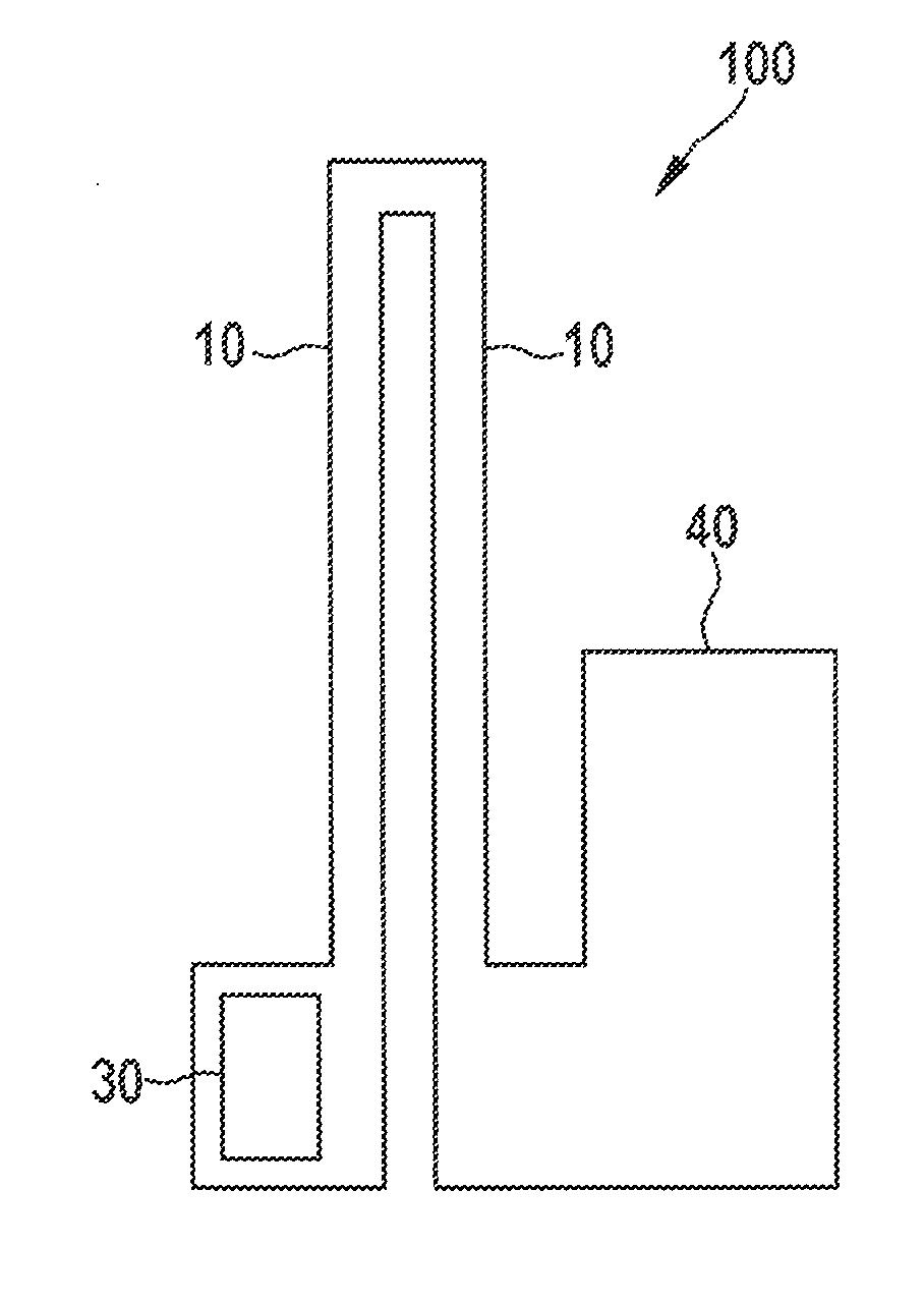
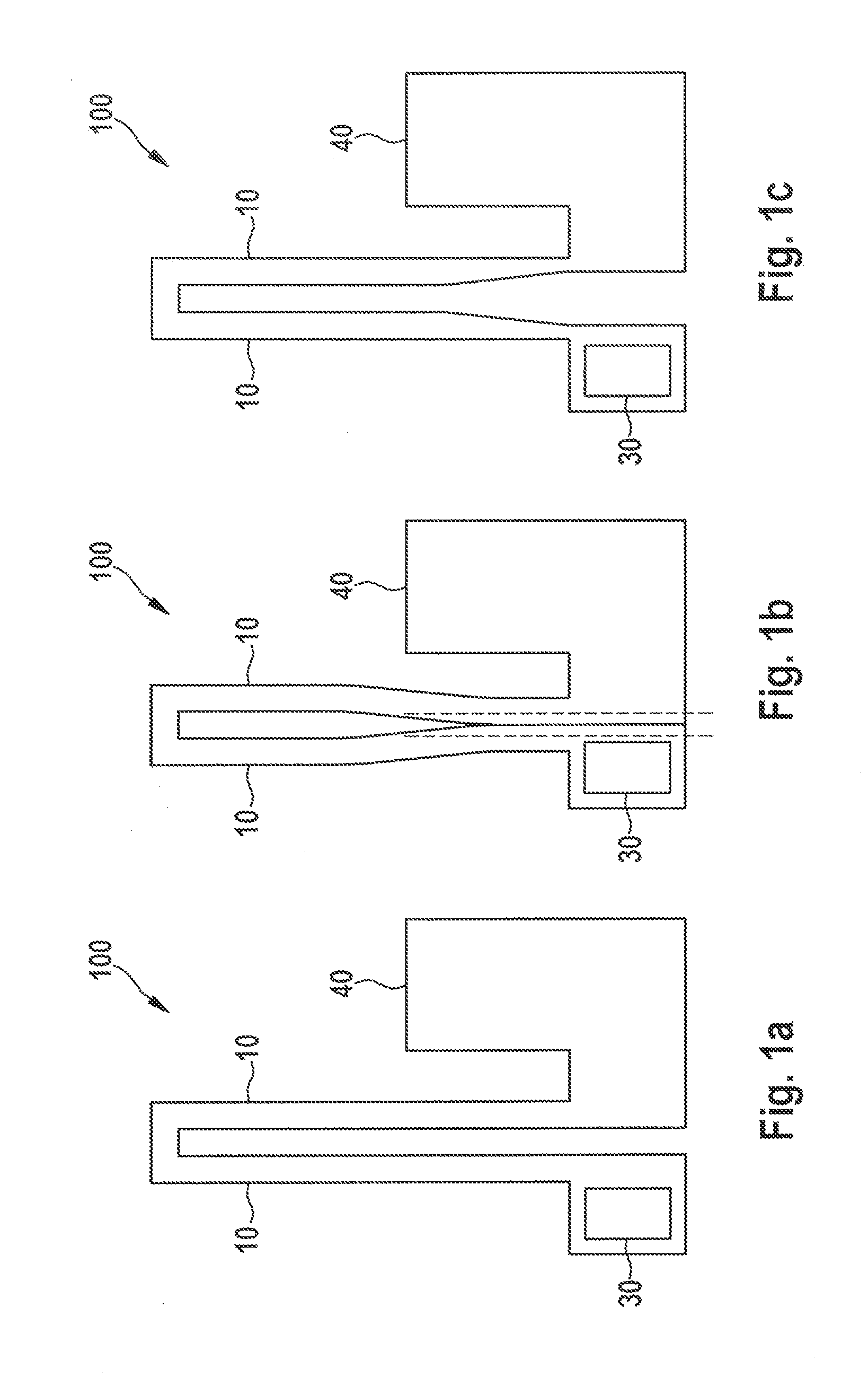
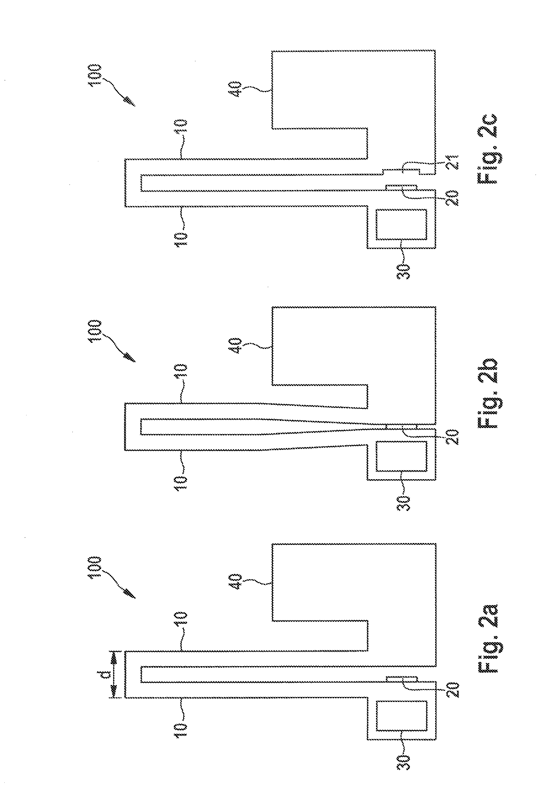
[0035]The present invention proposes to use a stop element 20, which realizes a type of wear reserve, in order to constructively protect locations of micromechanical spring mechanism 100 where mechanical contacts may arise in overload situations. In this way the material erosion will initially not lead to a weakening of the spring structures, but merely to an intentional material erosion at locations that are less relevant. Depending on the individual configuration, this makes it possible, for example, to absorb a few thousand up to a few 100,000 strike events, without causing significant weakening of active spring structures.

[0036]For the most part, the spring structures are situated at connection points that lie across from the fixed and the movable structures. In the present invention, the particular spots at which spring legs 10 may be contacted are reinforced by a stop element 10 in the form of a stop base or a stop nub or a sacrificial stop structure. This may be done in regio...


PUM

PropertyMeasurementUnit
Widthaaaaaaaaaa
Surface areaaaaaaaaaaa

Abstract

A micromechanical spring mechanism, having two spring legs, which essentially are disposed in parallel with one another; and at least one stop element, which is placed so as to prevent the two spring legs from striking each other.

Description

RELATED APPLICATION INFORMATION[0001]The present application claims priority to and the benefit of German patent application no. 10 2014 223 351.8, which was filed in Germany on Nov. 17, 2014, the disclosure of which is incorporated herein by reference.FIELD OF THE INVENTION[0002]The present invention relates to a micromechanical spring mechanism. Furthermore, the present invention relates to a method for manufacturing such a micromechanical spring mechanism.BACKGROUND INFORMATION[0003]Micromechanical inertial sensors, i.e., sensors having movable structures, such as rate of rotation sensors, acceleration sensors or micro mirrors, frequently use micromechanical springs on which seismic masses are suspended. In addition to their mass suspension function, these spring suspensions are also often employed as mechanical stops, in order to decelerate or restrict the movement in the event of an overload, and to thereby prevent the spring from being destroyed, such as fractured, for instanc...

Claims


Application Information

Patent Timeline
IPC IPC(8): F16F1/18F16F1/26
CPCF16F1/18F16F1/26F16F2238/022F16F2230/0047F16F2226/04G01D11/18G01P15/125G01P2015/0814B81B3/0051G01P15/0802G01P15/08
Inventor PRUETZ, ODD-AXELSPECHT, HENDRIKPUYGRAINER, ANTOINE
Owner ROBERT BOSCH GMBH
Learn More