Ball screw device having bearing spacer

a technology of ball bearings and screws, which is applied in the direction of gearing, hoisting equipments, gearing elements, etc., can solve the problems of generating great noise by the striking of balls, and preventing the ball bearing members from striking onto each other

Inactive Publication Date: 2008-12-11
HIWIN TECH
View PDF8 Cites 10 Cited by
  • Summary
  • Abstract
  • Description
  • Claims
  • Application Information

AI Technical Summary

Benefits of technology

[0018]The primary objective of the present invention is to provide a ball screw device including an endless ball train guiding passage formed therein for smoothly receiving and guiding the ball bearing members to move relative to the ball nut and the screw shaft, and a number of bearing spacers disposed between the ball bearing members for suitably spacing the ball bearing members from each other and for preventing the ball bearing members from striking onto each other and for silencing purposes.

Problems solved by technology

In Schlenker, the balls may be loosely received in the endless ball train guiding passage and are not spaced away from each other and may have a good chance to strike onto each other while moved along the endless ball train guiding passage of the ball nut, such that a great noise will be generated by the striking of the balls.
However, similarly, the balls may also be loosely received in the endless ball train guiding passage and are not spaced away from each other and also may have a good chance to strike onto each other while moved along the endless ball train guiding passage of the ball nut, such that a great noise will be generated by the striking of the balls.

Method used


Image

  • Ball screw device having bearing spacer
  • Ball screw device having bearing spacer
  • Ball screw device having bearing spacer

Examples


Embodiment Construction

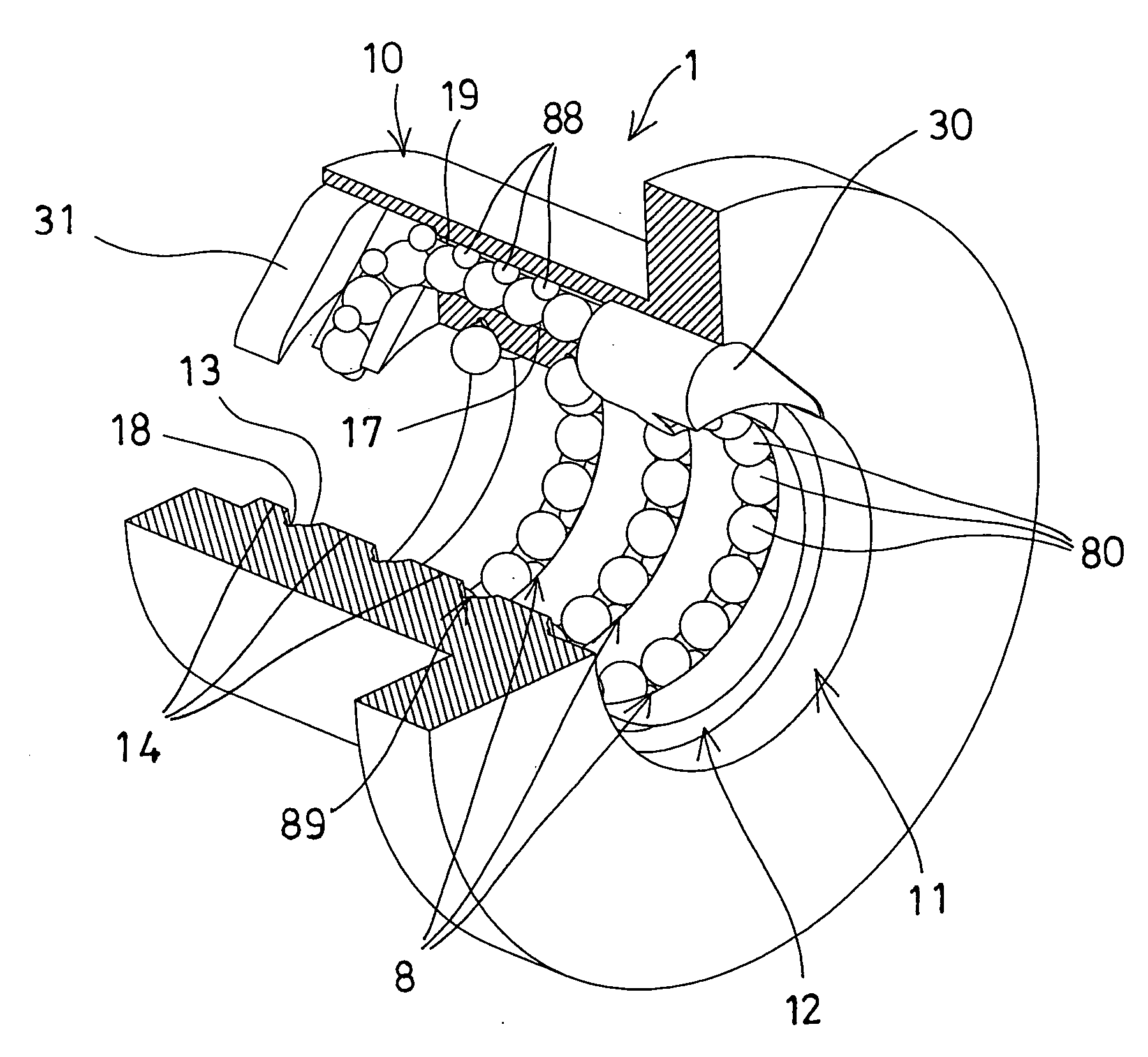
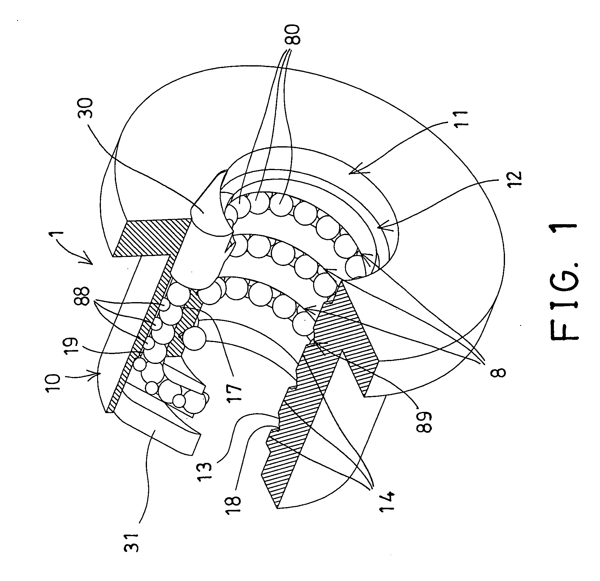
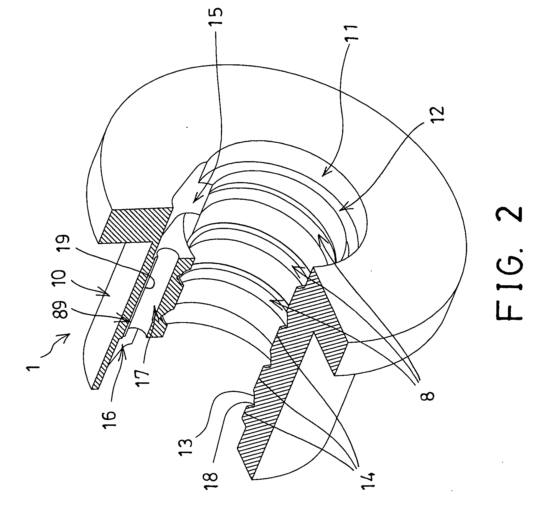
[0030]Referring to the drawings, and initially to FIGS. 1-2, a ball screw device 1 in accordance with the present invention comprises an outer ball nut 10 including a bore 11 formed therein and having an inner thread 12 formed therein, the inner thread 12 of the ball nut 10 includes a number of peripheral and helical groove portions 13 formed and defined by a number of peripheral and helical ridges 14 for threading with or for engaging with an outer thread of a typical screw shaft (not shown), and thus for allowing the ball nut 10 to be moved along the screw shaft, or for allowing the screw shaft to be rotated and moved relative to the ball nut 10. The threading engagement and / or the rotational engagement between the ball nut 10 and the screw shaft is typical and has been shown or disclosed in U.S. Pat. No. 5,014,568 to Schlenker, U.S. Pat. No. 5,063,809 to Schlenker, U.S. Pat. No. 5,193,409 to Babinski, U.S. Pat. No. 5,492,036 to Sato, U.S. Pat. No. 5,809,838 to Miyaguchi et al., a...


PUM


Abstract

A ball screw device includes a ball nut having an inner thread formed by a number of helical groove portions for forming an endless ball rolling passage in the ball nut and for receiving a number of bearing members, and an endless spacer moving passage formed in the ball nut and communicating with the endless ball rolling passage of the ball nut for receiving a number of bearing spacers which are engaged between the bearing members for spacing the bearing members away from each other and for preventing the bearing members from striking onto each other. The bearing spacers may be spherical bearing spacers, and made of synthetic materials.

Description

BACKGROUND OF THE INVENTION[0001]1. Field of the Invention[0002]The present invention relates to a ball screw device, and more particularly to a ball screw device having an endless ball train guiding passage formed therein for smoothly receiving and guiding the ball bearing members to move relative to the ball nut and the screw shaft, and a number of bearing spacers disposed between the ball bearing members for suitably spacing the ball bearing members from each other and for preventing the ball bearing members from striking onto each other and for silencing purposes.[0003]2. Description of the Prior Art[0004]Typical ball screw devices comprise a ball nut rotatably and / or moveably engaged onto a screw shaft, and normally arranged to allow the ball nut to be rotated and / or moved relative to the screw shaft in great rotational speeds. For allowing the ball nut to be smoothly rotated and moved relative to the screw shaft, a suitable bearing device or lubricating structure is further re...

Claims


Application Information

Patent Timeline
Patent Type & Authority Applications(United States)
IPC IPC(8): F16H25/22
CPCF16H25/2219Y10T74/19749F16H25/2238
Inventor LIU, CHIA MINLIN, KENNY
Owner HIWIN TECH
Why Eureka
Try Eureka