Method for building an underground continuous wall

a continuous wall and underground technology, applied in the direction of mechanical machines/dredgers, soil conditioning compositions, transportation and packaging, etc., can solve the problems of using continuous walls as cutoff walls, walls cannot have a water cutoff function along the vertical direction, and vertical extension continuous walls can be built vertically

Inactive Publication Date: 2000-10-31
KOBELCO CONSTR MASCH CO LTD
View PDF26 Cites 32 Cited by
  • Summary
  • Abstract
  • Description
  • Claims
  • Application Information

AI Technical Summary

Problems solved by technology

However, according to this technique, only vertically extending continuous walls can be built.
Therefore, such walls cannot have a water cutoff function along vert

Method used


Image

  • Method for building an underground continuous wall
  • Method for building an underground continuous wall
  • Method for building an underground continuous wall

Examples


Embodiment Construction

Embodiments of the invention are described with reference to the accompanying drawings.

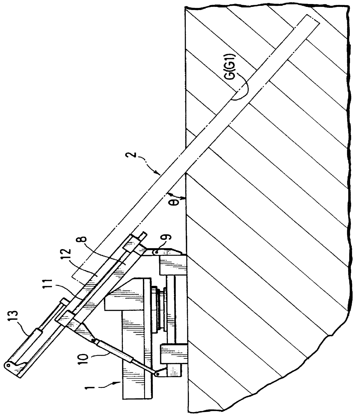
FIG. 1 shows an overall construction of an excavator (continuous wall building apparatus) for excavating a continuous trench which serves as a base of an underground continuous wall.

This excavator is basically constructed such that a chain cutter 2 is mounted on a running carriage (e.g. a base machine of a crawler crane) 1 capable of running by itself. A continuous trench G of specified length is excavated by moving the cutter 2 in a transverse direction while rotating it with the cutter 2 placed in a hole dug by a suitable means such as a hydraulic shovel.

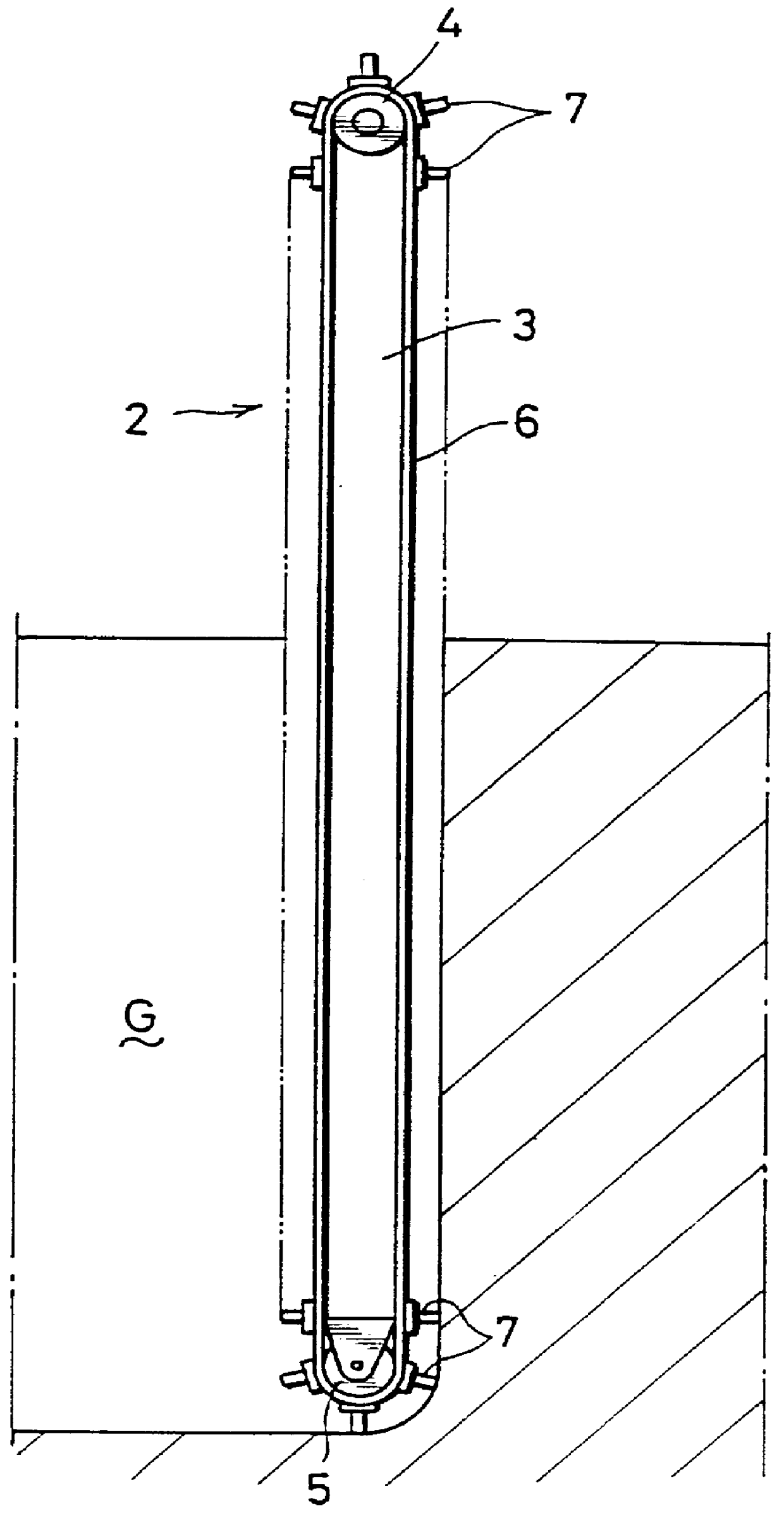
The cutter 2 is, as shown in FIG. 2, constructed such that an endless chain 6 is fitted between a drive wheel (sprocket) 4 provided at an upper end of a cutter post 3 which is a vertically long boxlike frame and a driven wheel (pulley) 5 at a bottom end thereof and a multitude of excavation blades 7 are provided on the outer surface of the chain...


PUM


Abstract

PCT No. PCT/JP96/03647 Sec. 371 Date Aug. 13, 1997 Sec. 102(e) Date Aug. 13, 1997 PCT Filed Dec. 13, 1996 PCT Pub. No. WO97/21877 PCT Pub. Date Jun. 19, 1997An underground continuous wall building method and apparatus in which a chain cutter 2 provided with excavation blades is obliquely mounted on a running carriage 1. Slanting continuous trenches G1, G2 are excavated by moving the running carriage 1 in a transverse direction while rotating the cutter 2 with the cutter 2 obliquely placed in the ground, and a water cutoff material is poured into the excavated continuous trenches G1, G2 and solidified therein to build slanting continuous walls R1, R2 in the ground.

Description

BACKGROUND OF ART1. Field of the InventionThe present invention relates to underground continuous wall building method and apparatus for building a variety of continuous walls in the ground for water cutoff purpose, reinforcing purpose and other purposes.2. Description of Background ArtAs a technique for building an underground continuous wall, there has been conventionally known a method according to which a chain cutter is vertically mounted on a running carriage (e.g. a base machine of a crawler crane), the running carriage is moved in a transverse direction while the cutter is rotated, thereby excavating a continuous trench of a fixed width, and a continuous wall is built by pouring a wall material such as cement or concrete into this continuous trench and solidifying it therein or by inserting a concrete panel therein (refer to Japanese Unexamined Patent Publication Nos. 5(HEI)-280043 and 5(HEI)-280044.The cutter is constructed such that an endless chain is fitted between upper...

Claims


Application Information

Patent Timeline
IPC IPC(8): E02D17/00E02D17/13E02D5/18E02D5/20E02F5/06
CPCE02D5/18E02D17/13E02D5/187
Inventor KOIKE, KENJIINAGAKI, YOSHIAKIAOI, MINORUKINOSHITA, FUMIOASHIDA, SHIGEKINAKAJIMA, YUJIKOMOTO, TATSUOKONDO, HIROAKI
Owner KOBELCO CONSTR MASCH CO LTD
Why Eureka
Try Eureka