An endoscope accessory

an endoscope and accessory technology, applied in the field of endoscope accessories, can solve the problems of poor image quality, hammering the obtaining of ultrasonic images, and insufficient contact between the transducer balloon and the intestinal wall, and achieve the effect of enhancing the ability of the endoscope to maintain luminal view

Inactive Publication Date: 2016-03-24
IZOMED INC
View PDF13 Cites 7 Cited by
  • Summary
  • Abstract
  • Description
  • Claims
  • Application Information

AI Technical Summary

Benefits of technology

[0010]The endoscope accessory embodying this invention enhances capabilities of an endoscope in maintaining luminal view and is comprised of a flexible elongated sheet, sized to envelop a flexible endoscope or echoendoscope shaft and envelop an endoscope or echoendoscope shaft without need to remove endoscope from the body when its opposed longitudinal edge portions coacting to form a flexible overtube receiving therewithin the endoscope or echoendoscope shaft. The longitudinal edges of the endoscope accessory overlap forming a seam and are supplied with an adhesive along its entire length for coacting with the opposed edge portions to form a liquid tight seam along the entire length of the overtube. The adhesive is covered by a release sheet that can be removed before adhering the two longitudinal end portions. Alternative to use adhesive at the longitudinal edges of the endoscope accessory for creating the longitudinal seam, the overtube seam can be closed along its entire length using a plurality of spaced magnets on the longitudinal edge portions of the endoscope accessory sheet that are attracting the other magnets interspersed on the other longitudinal edge portion. In order to avoid activation of the magnets before placing the endoscope shaft within the overtube, at least one longitudinal edge portion is supplied with a longitudinal magnet cover. Preferably, both longitudinal edge portions are provided with a cover. The magnets can only coact with the opposed longitudinal edge portion magnets when the magnet covers are removed from the edge portion or portions.

Problems solved by technology

Air, however, creates a barrier to ultrasonic wave passage and hampers the obtaining of ultrasonic images.
In most parts of the gastrointestinal tract, however, the large diameter of the lumen and / or the angle of the transducer in relation to the intestinal wall results in an inadequate contact between the transducer balloon and the intestinal wall.
Unfortunately, the gastrointestinal tract is not a closed region and the infused water soon moves to other regions of the gastrointestinal tract.
This can often result in poor image quality despite repeated infusion of water around the transducer.
In addition, infusion of significant amounts of water during the examination could result in untoward problems such as aspiration of the water into the patient's airway or overdistention of the gastrointestinal tract.
However, it does not have any positioning balloon for securing the position within the gastrointestinal lumen, it does not use a magnet or an adhesive for closure and it has special interlocking members that need to be aligned and locked using a fastener.
Thus, it cannot create a liquid tight space at the end of the overtube.
This prevents this device to work similar to my device, which has a straight distal end in the gastrointestinal (GI) tract.
Also, there is no structure in the overtube that can create a hydraulic seal between the endoscope and overtube.
Not to mention that the device is not designed to achieve a hydraulically sealed region due to the lack of any structure in the overtube to seal the endoscope within the overtube.
In addition, Chu et al. device does not have a catheter that terminates in an inflatable occlusion balloon as an integral part of the described overtube.
The Chu et al. device fails to teach a structure that creates a seal inside the overtube and around the endoscope since the distal end of the endoscope at most abuts clear window or if there is no clear window, the tip of the endoscope cannot go beyond the overtube.

Method used


Image

  • An endoscope accessory
  • An endoscope accessory
  • An endoscope accessory

Examples


Embodiment Construction

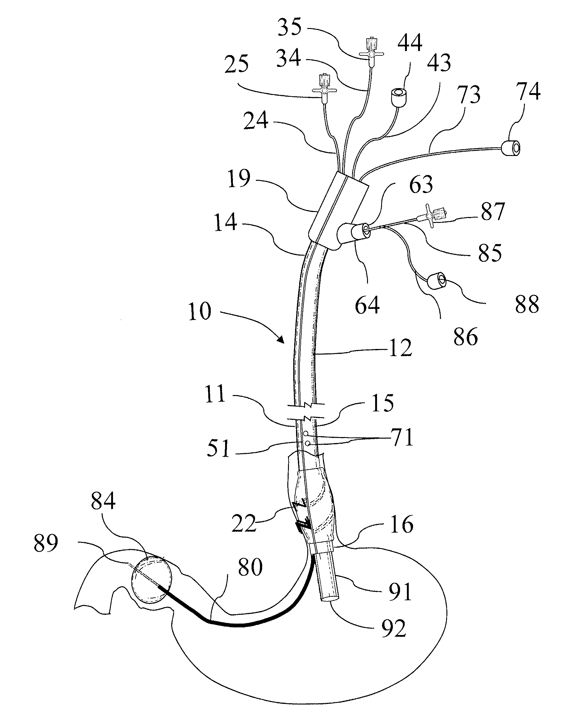
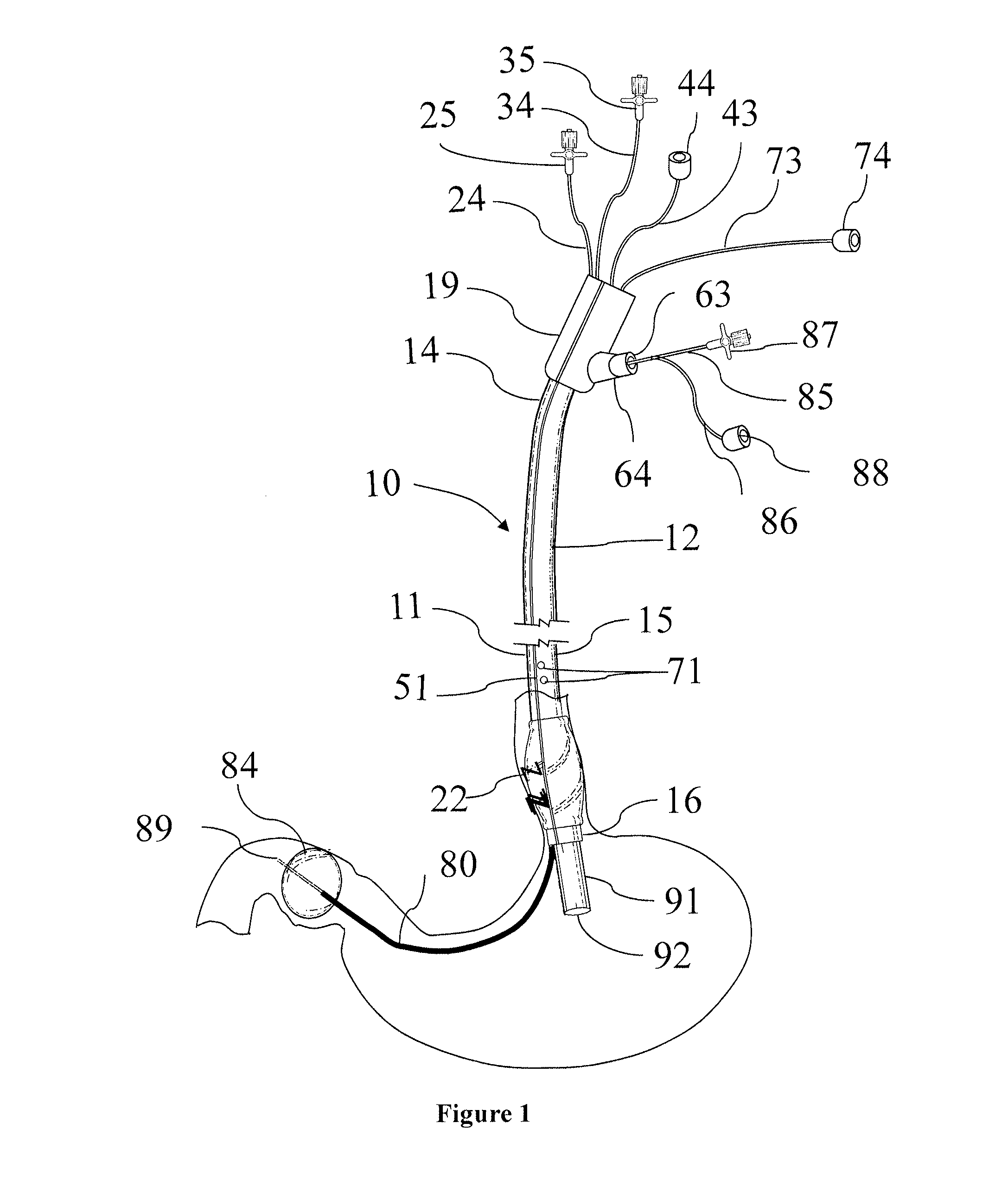
[0049]Endoscope Accessory 10 has the following components:

[0050]A—Overtube: As it is depicted in FIG. 1, an overtube 11 defines a central through passageway for receiving therewithin an endoscope or echoendoscope shaft 91 and then is inserted inside a body cavity such as gastrointestinal tract.

[0051]The overtube 11 has an external 12 surface and an internal surface (not shown in FIG. 1), a proximal end portion 14, a midportion 15 and a distal end portion 16. The overtube 11 is also supplied with a handle 19 at its proximal end portion 14. Several catheters exit from the handle 19. These catheters are used for connection to inflation devices, suction devices or passage of therapeutic tools through the overtube 11.

[0052]The length of the overtube 11 is long enough so that when the distal overtube end portion 16 is secured inside the body cavity, the overtube proximal end portion 14 stays out of the body cavity and allows grasping of the handle 19 and manipulation of the overtube 11 fo...


PUM


Abstract

An endoscope accessory comprises a flexible sheet wrapped around the endoscope shaft to form a flexible overtube. The overtube has an inflatable positioning ring just proximal to the tip of the endoscope or echoendoscope to secure the position of the overtube within the body cavity. The overtube also has a sealing band within the internal surface of the overtube that when inflated create a seal around the endoscope shaft. Another part of the device is the catheter with an occlusion balloon at its free end portion that is carried by the overtube and extends beyond the tip of the endoscope. Inflation of the positioning ring, sealing band and occlusion balloon defines an examination compartment within the body cavity at the tip of the endoscope that can be filled with air or water for improving the quality of the endoscopic examination with regular endoscope of echoendoscope.

Description

CROSS-REFERENCE TO RELATED APPLICATION[0001]This application is a continuation-in-part of U.S. Ser. No. 13 / 900,524 filed on May 22, 2013 which, in turn, is a continuation-in-part of U.S. Ser. No. 12 / 266,953 filed on Nov. 7, 2008, both incorporated herein by reference.FIELD OF INVENTION[0002]This invention relates generally to an accessory for endoscopic examination of body organs, particularly the gastrointestinal tract. More so, the invention relates to the creation of an examination compartment around the tip of an endoscope introduced into a visceral organ.BACKGROUND OF INVENTION[0003]An endoscope is a well-known optical system for evaluation of internal organs disclosed and claimed in U.S. Pat. No. 3,449,037 to C. J. Koester. Currently used fiber optic endoscopes are comprised of lenses mounted in a flexible tube to relay an image from inside a body cavity for viewing by a physician for diagnosis or manipulation inside cavitary spaces. An echoendoscope (EUS) is a device that com...

Claims


Application Information

Patent Timeline
Patent Type & Authority Applications(United States)
IPC IPC(8): A61B1/00A61B8/12
CPCA61B1/00135A61B1/00082A61B1/0014A61B1/00154A61B8/12A61B1/005A61B1/015A61B1/2736A61B1/00148
Inventor FARHADI, ASHKAN
Owner IZOMED INC
Why Eureka
Try Eureka