Method and apparatus for determining the alignment of motor vehicle wheels

a technology for determining the alignment and motor vehicles, which is applied in the direction of measuring devices, instruments, using fluid means, etc., can solve the problems of excessive or uneven wear of the tires of the vehicle, adversely affecting the handling and stability of the vehicle, and the extent of the inaccuracy by which these components are mounted

Inactive Publication Date: 2000-11-21
SNAP ON INC
View PDF9 Cites 148 Cited by
  • Summary
  • Abstract
  • Description
  • Claims
  • Application Information

AI Technical Summary

Problems solved by technology

The wheels of a motor vehicle need to be periodically checked to determine whether or not they are in alignment with each other because, if any of the wheels are out of alignment, this can result in excessive or uneven wear of the tires of the vehicle and/or adversely affect the handling and stability of the vehicle.
1. The vehicle is driven onto a test bed or rack which has previously been levelled to ensure a level base for the vehicle.
2. Some components of the alignment determination apparatus are mounted onto the wheels of the vehicle. These components are not necessarily accurately placed with respect to the wheel axis. The extent of the inaccuracy by which these components are mounted is called the "mounting error".
3. A "runout" calculation is done by jacking the vehicle up and rotating each wheel and taking measurements of the orientation of that wheel at different positions. These measurements are then used to calculate a correction factor to compensate for the "mounting error" and actual rim run-out.
4. A determination of the alignment of each of the wheels is done. The results of these determinations are compared to the specifications of alignment parameters for the vehicle being tested.
5. The operator then adjusts the various linkages of each wheel to correct for the misalignment, if any, of the wheels.
6. Steps 4 and 5 are repeated until the alignment is up to standard and/or is within man

Method used


Image

  • Method and apparatus for determining the alignment of motor vehicle wheels
  • Method and apparatus for determining the alignment of motor vehicle wheels
  • Method and apparatus for determining the alignment of motor vehicle wheels

Examples


Embodiment Construction

Basic Theory of the Invention

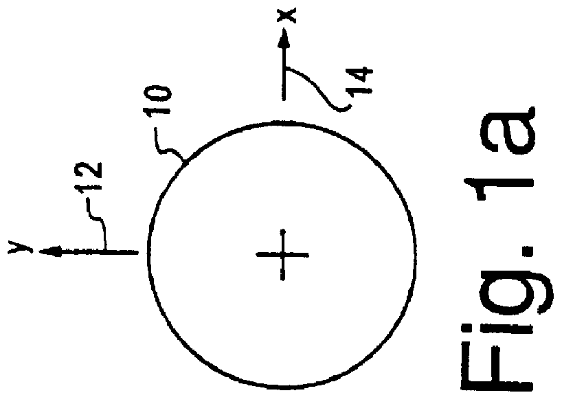
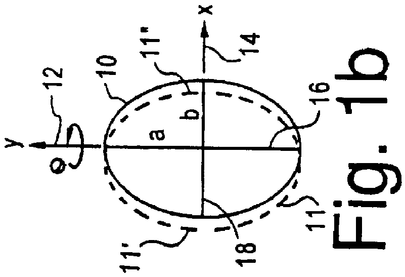
This invention is based on the fact that the image of a body varies according to the perspective from which such body is viewed and that the variation in the image is directly related to and determinable from the perspective angle of the view path along which the body is viewed.

Furthermore it is known that it is possible to determine the perspective angles at which an object is viewed merely by relating the perspective image of that object with a true non-perspective image thereof. Conversely put, it is possible to determine the angles at which an object is orientated to a view path (or a plane perpendicular thereto) by comparing a perspective image of an object with a non-perspective image thereof.

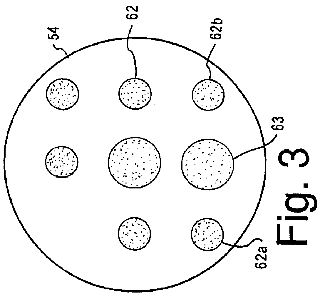
This is illustrated in FIGS. 1(a)-(c) with reference to a circle 10, shown as it would appear if viewed from three different perspectives. In FIG. 1(a) the circle 10 is illustrated as it would appear if it were viewed along an axis perpendicular to its primary...


PUM


Abstract

An apparatus for determining the position and/or alignment of objects such as motor vehicle wheels, and including targets for attachment to the objects, a pair of optical sensing means such as television cameras for viewing the targets, an electronic processing means connected to the optical sensing means for processing data relating to images of the targets to determine position and/or alignment information, and a display means for displaying the position and/or alignment information. The optical sensing means view a target located on each object and form an image of each target. Electronic signals corresponding to each of the images are transferred to the electronic processing means which correlates the image signals of each of the targets with the true shape of each target. In so doing, the processing means relates the geometric characteristics and positional interrelationships of certain known elements of the target with the geometric characteristics and positional interrelationships of corresponding elements in the viewed images and calculates the position and/or alignment of the objects to which the targets are attached.

Description

Field of the InventionThis invention relates to a method and apparatus for determining the alignment of motor vehicle wheels. More particularly, this invention relates to a method and apparatus including an opto-electronic image detector for detecting wheel orientation and producing electronic image data representing the wheels, or a reference mounted thereon, computational means for determining the alignment of the wheels, and means for comparing the electronic images, or data corresponding thereto, to previously stored alignment data and generating information which can be used to perform necessary adjustment to the vehicle.Terms and DefinitionsIn the vehicle wheel alignment industry the following terms, with corresponding definitions, are commonly used:Camber is the angle representing the inward or outward tilt from true vertical of the wheel and is positive if the top of the wheel tilts outward.Caster is the angle representing the forward or rearward tilt from true vertical of t...

Claims


Application Information

Patent Timeline
IPC IPC(8): G01B11/275
CPCG01B11/2755G01B2210/12G01B2210/30G01B2210/26G01B2210/143
Inventor JACKSON, BERNIE FERGUS
Owner SNAP ON INC
Why Eureka
Try Eureka