Deployment mechanisms for aircraft auxiliary airfoils

a technology of auxiliary airfoils and deployment mechanisms, which is applied in the direction of aircraft components, wing adjustments, and aircraft without power amplication, etc., can solve the problems of compromising fuel carrying space within the main airfoil, excessive weight and added aerodynamic penalties, and the inability of beams to be mounted on the main airfoil

Inactive Publication Date: 2000-11-21
AIRBUS OPERATIONS LTD
View PDF14 Cites 54 Cited by
  • Summary
  • Abstract
  • Description
  • Claims
  • Application Information

AI Technical Summary

Problems solved by technology

Owing to the rack forming a toothed surface in the upper boom of the I-beam rearwardly of the straddle rollers, an upper rear roller for supporting the I-beam could not be mounted on the main airfoil for contact with an upper surface of the I-beam owing to the lack of a smooth upper rolling track because of the presence of the rack

Method used


Image

  • Deployment mechanisms for aircraft auxiliary airfoils
  • Deployment mechanisms for aircraft auxiliary airfoils
  • Deployment mechanisms for aircraft auxiliary airfoils

Examples


Embodiment Construction

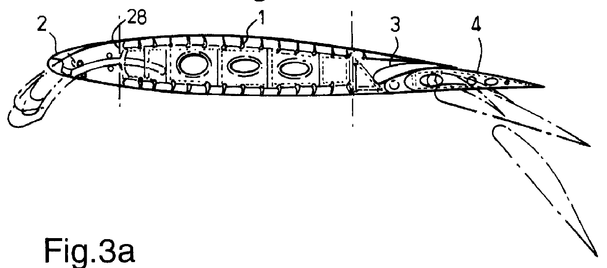
Referring to the drawings, FIG. 1 shows in a chordwise section an aircraft wing having a main airfoil or wing box 1 to which are movably attached auxiliary airfoils in the form of a leading edge slat 2 and trailing edge flaps 3 and 4. Both slat 2 and flaps 3, 4 are movable between stowed or cruise positions shown in normal outline and at least two deployed positions shown in chain dotted line.

This document will concentrate on a mechanism for deploying a leading edge slat and the remaining figures of the drawings illustrate slats and their operating mechanisms.

FIG. 3a shows the slat 2 in its retracted or cruise position and FIG. 3b shows the slat in its extended or fully deployed position. A number of intermediate positions may be available according to flight requirements.

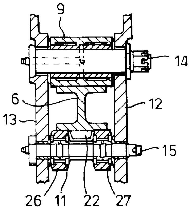
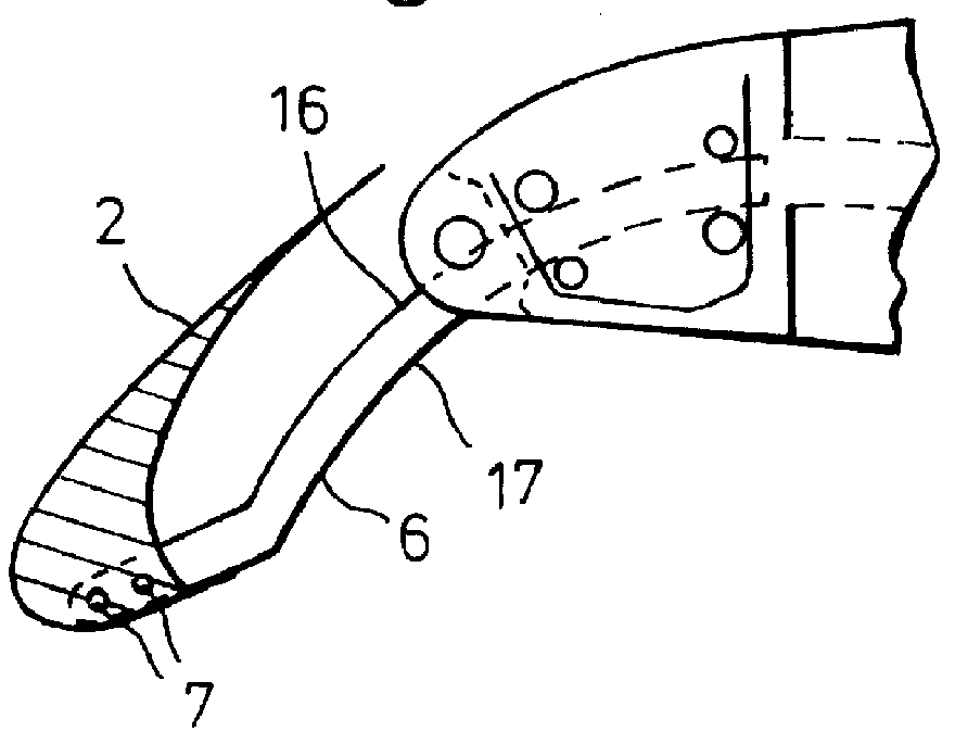
Referring to FIGS. 3a, 3b and 4 in particular, the slat 2 is supported with respect to the main airfoil 1 by means of an I-section beam 6. The beam 6 is affixed at one end to the slat 2 by means of fasteners 7. The...


PUM


Abstract

A deployment mechanism for moving an aircraft wing leading edge slat (2) or trailing edge flap (4) relative to a main airfoil (1) is provided. The mechanism includes an I-section support beam (6) extending between the main airfoil (1) and the slat (2) or flap (4). The support beam (6) is driven into and out of the main airfoil (1) by a rack and pinion mechanism (22, 23), the rack (22) being disposed along a lower boom (20) of the beam (6) and the beam (6) being supported for rolling contact with the main airfoil (1) by upper and lower straddle rollers (8, 9, 10, 11) positioned between wing leading edge ribs (12, 13). Roller tracks (16, 17, 18) extend along upper and lower booms (19, 20) of the beam with at least one roller track (17, 18) co-extending with the rack (22) adjacent thereto along the beam.

Description

BACKGROUND TO THE INVENTIONThis invention relates to deployment mechanisms for moving aircraft auxiliary airfoils such as leading edge slats or trailing edge flaps relative to main airfoils. In particular the invention relates to such mechanisms which include support beams extending between auxiliary and main airfoils in which the beam is driven by a rack and pinion arrangement.DESCRIPTION OF PRIOR ARTIt is well known to modify the lift of an aircraft main aerofoil when the aircraft is moving at lower speeds, for example during take off and approach or landing, to delay the point at which wing stall occurs. Auxiliary airfoils are used for this purpose which are moveable between a retracted or cruise position closely adjacent to the main airfoil where minimum aerodynamic drag is created and at least one deployed position spaced from the main airfoil when modified wing lift is created.Various types of deployment mechanism for moving the auxiliary airfoil as described above are known. ...

Claims


Application Information

Patent Timeline
IPC IPC(8): B64C13/34B64C13/00B64C9/28B64C9/00
CPCB64C13/34B64C9/28
Inventor JAGGARD, PHILIP R.
Owner AIRBUS OPERATIONS LTD
Why Eureka
Try Eureka