Engine exhaust control

a technology of exhaust control and control system, which is applied in the direction of electric control, machine/engine, output power, etc., can solve the problems of difficult valve operation, battery storage and retaining little power, and small snowmobiles that do not have batteries to power electrical accessories

Inactive Publication Date: 2000-12-05
YAMAHA MOTOR CO LTD
View PDF18 Cites 34 Cited by
  • Summary
  • Abstract
  • Description
  • Claims
  • Application Information

AI Technical Summary

Problems solved by technology

Additionally, small snowmobiles do not have batteries to power electrical accessories when the engine is not operating; such accessories are powered by a generator when the snowmobile engine has been started.
Larger snowmobiles may have batteries; however, due to the unusually cold operating environments that these vehicles are subjected to, the batteries may store and retain little power.
Because these valves have a relatively small range of movement, and are not continuously moved, they may seize within the guide passage in which they are mounted.
Such seizure may result due to deposits that form on the valve bodies.
Specifically, because these valves are normally employed in two cycle engines and because oil is typically mixed with the air and fuel charge ported into the c

Method used


Image

  • Engine exhaust control
  • Engine exhaust control
  • Engine exhaust control

Examples


Embodiment Construction

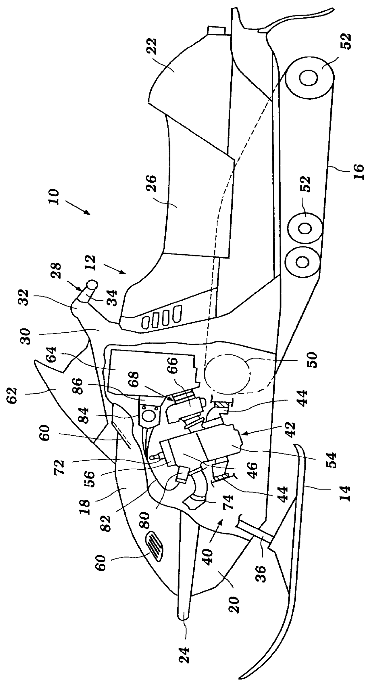
The present exhaust timing control system and control unit have particular utility with snowmobiles, and thus, the following describes such a system and unit in the context of an exemplary snowmobile. This environment of use, however, should be considered exemplary. The present exhaust timing control system and control unit can be readily adapted by those of skill in the art for use with other types of vehicles as well, such as tracked vehicles used extensively in cold temperature climates.

With reference now to FIG. 1, an exemplary snowmobile, indicated generally by the reference numeral 10, will be introduced to provide an environmental framework within which the present invention will be described. The snowmobile 10 generally comprises a body 12 that is supported at a forward portion by a pair of skis 14 and is driven from a rear portion by a track 16. The body 12 may be of any known construction and when it is referred to herein as a "body", it is to be understood that this term ...


PUM


Abstract

A snowmobile is powered by an internal combustion engine. The engine has an exhaust timing control valve, a control unit and a generator. The control unit determines the positioning of the control valve as a function of engine speed. Additionally, the control unit initiates a control valve cleaning cycle when the engine speed first exceeds a first predetermined speed within a predetermined range of engine speeds. The first predetermined speed is desirably an engine speed at which the generator generates sufficient power to render the control unit operable. The control unit retracts the control valve when the engine speed exceeds the upper limit of the predetermined range. Thereafter, the control unit initiates another control valve cleaning cycle when the engine speed decreases below a second predetermined engine speed.

Description

1. Field of the InventionThe present invention relates to an exhaust timing control system and control unit. More particularly, the present invention relates to an exhaust timing control system and control unit of a snowmobile.2. Description of Related ArtSnowmobiles are powered by internal combustion engines, particularly two stroke engines. Additionally, small snowmobiles do not have batteries to power electrical accessories when the engine is not operating; such accessories are powered by a generator when the snowmobile engine has been started. Larger snowmobiles may have batteries; however, due to the unusually cold operating environments that these vehicles are subjected to, the batteries may store and retain little power.The conventional two stroke engines which power snowmobiles generally include an exhaust port provided in each cylinder wall such that spent gases are exhausted through the exhaust port as the piston reciprocates in the cylinder. Exhaust port timing has an imp...

Claims


Application Information

Patent Timeline
IPC IPC(8): F02D13/02F02P1/02F02B25/20F02D9/04F02D11/10F02D17/00F02D45/00
CPCF02D13/0249F02D13/0284Y02T10/18Y02T10/12
Inventor UCHIDA, YOSHIAKI
Owner YAMAHA MOTOR CO LTD
Why Eureka
Try Eureka