
Collapsible and convertible walker for disabled persons

a walker, convertible technology, applied in the field of walker equipment for disabled persons, can solve the problems of requiring dexterity of the disabled operator, affecting the safety of the disabled person, and affecting the safety of the disabled person, and achieve the effect of high safety standard

Inactive Publication Date: 2000-12-19
CORNEAU MICHEL
View PDF16 Cites 55 Cited by
  • Summary
  • Abstract
  • Description
  • Claims
  • Application Information

AI Technical Summary

Benefits of technology

Another feature of the present invention is to provide a walker apparatus which is collapsible and which is easy to transport and which may be used in the overhead storage compartments of aircraft or public transport vehicles, and which can easily fit in the trunk of a car or on the seat of a car and wherein it is easy to position from a storage collapse condition to a condition of use.
Another feature of the present invention is to provide a walker apparatus which may be used by persons which are momentarily disabled, such as a person in rehabilitation.

Problems solved by technology

There are several disadvantages to such devices, one being that they are bulky and difficult to transport, for example in the trunk of a car or on the seat of a car and most of these are not transportable on public transport vehicles such as buses and airplanes as they cannot fit in overhead storage compartments provided in such vehicles.
Further, many of these apparatus resemble wheelchairs and do not provide a means for the disabled person to perform an exercise which is beneficial to his impairment.
Another disadvantage of these prior art devices is that some of these, such as that disclosed in U.S. Pat. No. 5,167,597, are unstable and require the disabled operator to have dexterity in order to control same.
Some of these also have their center of gravity too high.

Method used


Image

  • Collapsible and convertible walker for disabled persons
  • Collapsible and convertible walker for disabled persons
  • Collapsible and convertible walker for disabled persons

Examples


Embodiment Construction

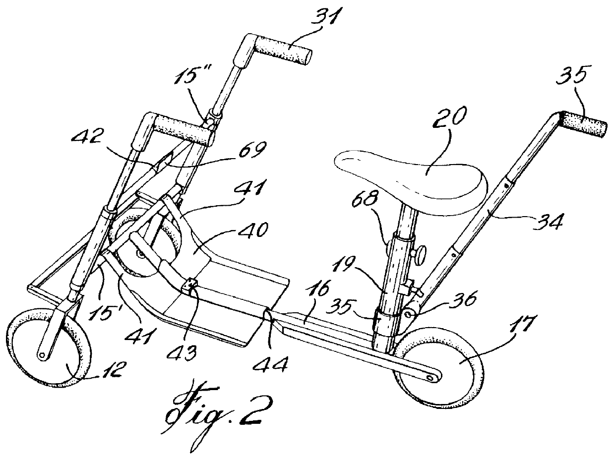
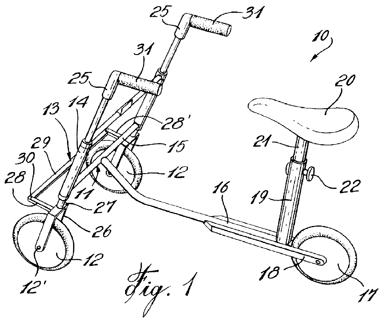
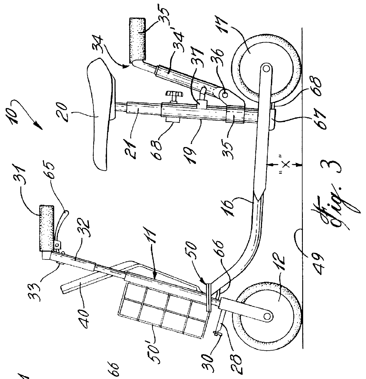
Referring now to the drawings, and more particularly to FIG. 1, there is shown generally at 10 the construction of the walker apparatus of the present invention suitable for a disabled user person. The apparatus comprises a frame having a front end section 11 to which is secured a pair of spaced-apart wheels 12 which are connected by a steering assembly having a tandem connecting linkage 13. The front end section also has opposed vertical guide tubes 14 and an intermediate connecting frame 15 secured between the vertical guide tubes. A rear frame section is comprised of a straight tubular frame 16 secured transversely of the intermediate connecting frame 15 and extending rearwardly from a bottom end thereof. A rear support wheel 17 is secured between a rear fork 18 of the frame 16 and disposed behind a vertical seat supporting tubular frame member. A seat 20 is mounted on a telescopic rod 21 which is received in a top end of the vertical seat support tubular frame member 19 and arre...


PUM


Abstract

A walker apparatus for disabled persons having a frame having a pair of spaced-apart wheels mounted at a front end thereof. A seat is secured to the frame rearwardly of the front end. The wheels are connected to a steering assembly having a tandem connecting linkage to cause the wheels to turn in parallel relationship. Handles are secured to the steering assembly to control the position of the wheels for guiding the apparatus during displacement thereof. A rear support wheel is secured to the frame and disposed behind the seat and substantially central between the pair of spaced apart wheels. The apparatus is motorized by the feet of the disabled person when sitting on the seat and grasping the steering handles. The walker apparatus may also be collapsible and may also be provided with a retractable pusher arm secured behind the seat whereby the apparatus may be displaced by an attendant person pushing the apparatus while the disabled person is seated on the seat with his feet disposed on a retractable foot rest plate.

Description

The present invention relates to a walker apparatus for a disabled person and more particularly to a collapsible and convertible walker apparatus which is easy to store and transport and which may be used solely by the disabled person which imparts movement and steering of the walker or which may be displaced by an attendant person pushing on a retractable pusher arm disposed behind the apparatus.Walker-type apparatus for disabled persons are known and examples of these may be found in issued U.S. Pat. Nos. 3,488,088, 4,861,051, 5,158,313, 5,167,597, and 5,741,020. There are several disadvantages to such devices, one being that they are bulky and difficult to transport, for example in the trunk of a car or on the seat of a car and most of these are not transportable on public transport vehicles such as buses and airplanes as they cannot fit in overhead storage compartments provided in such vehicles. Further, many of these apparatus resemble wheelchairs and do not provide a means for...

Claims


Application Information

Patent Timeline
IPC IPC(8): A61H3/04A61H3/00B62K5/00B62K15/00B62K3/00B62K5/04B62K3/16
CPCA61H3/04B62K15/00B62K3/16B62K5/023A61H2003/046A61H2201/0161A61H2201/1633
Inventor CORNEAU, MICHEL
Owner CORNEAU MICHEL
Features
  • Generate Ideas
  • Intellectual Property
  • Life Sciences
  • Materials
  • Tech Scout
  • Unparalleled Data Quality
  • Higher Quality Content
  • 60% Fewer Hallucinations
Learn More