Machine for Forming Containers

a technology for forming containers and containers, applied in the field of forming containers, can solve the problems of low operating risk of respective operators, and achieve the effect of facilitating the correction of positions in the heating modul

Inactive Publication Date: 2009-04-23
KRONES AG
View PDF7 Cites 10 Cited by
  • Summary
  • Abstract
  • Description
  • Claims
  • Application Information

AI Technical Summary

Benefits of technology

[0017]Finally, an expedient embodiment is so conceived that the auxiliary drive is adapted to be driven in both directions of rotation so that position corrections in the heating module can be carried out more easily.

Problems solved by technology

The safety standard is high, since, although work is simultaneously done at the blowing module and at the heating module, the operational risks for the respective operator are low.

Method used


Image

  • Machine for Forming Containers
  • Machine for Forming Containers
  • Machine for Forming Containers

Examples


Embodiment Construction

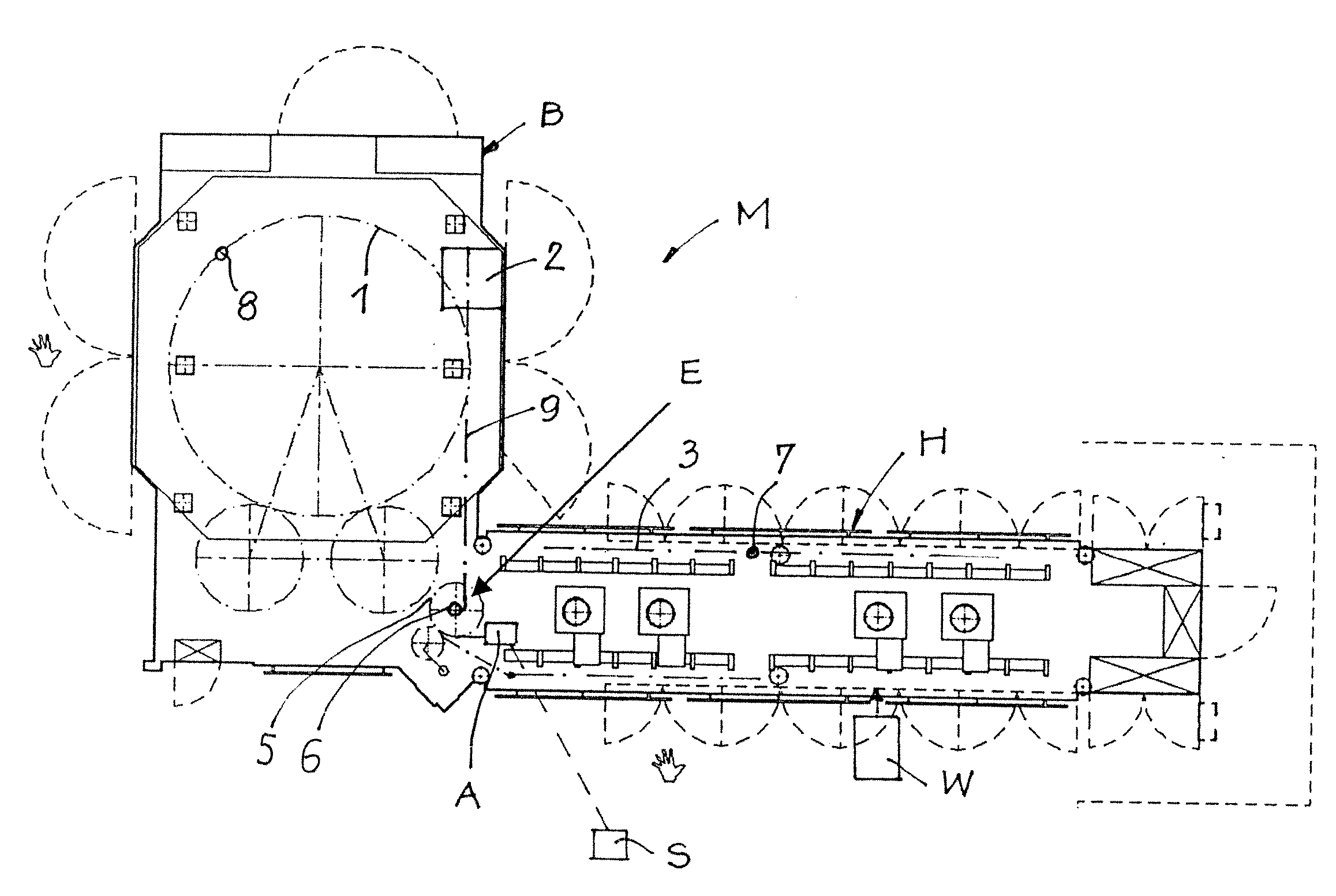
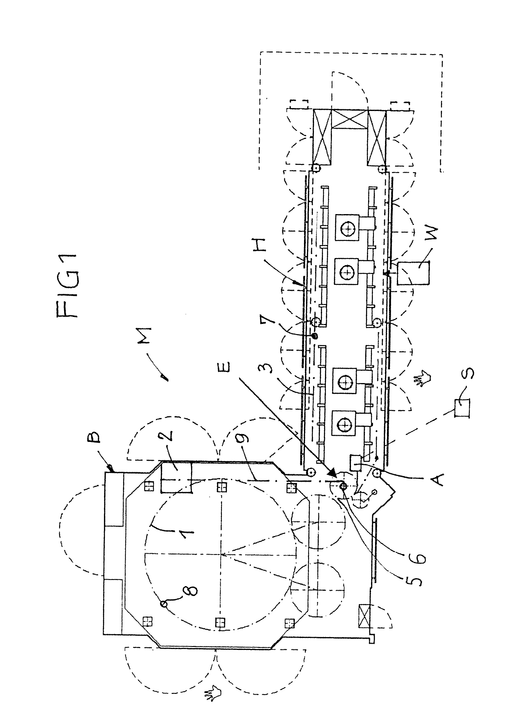
[0022]FIG. 1 shows a schematic top view of a machine M for forming containers, e.g. a blow moulding machine for continuously blowing or stretch blowing plastic bottles from plastic preforms. In the embodiment shown, a blowing module B is functionally coupled to the heating module H, said heating module H supplying to the blowing module B preforms which have been subjected to a temperature treatment (heating / cooling); these preforms are blown so as to form containers in said blowing module B and are then supplied, if desired, to a unit for further processing. It would be possible to combine more than one blowing module B with a heating module H, or a plurality of heating modules H with a blowing module B.

[0023]The blowing module B contains a rotor 1 which is adapted to be driven by a main drive 2 either permanently or in a clocked mode of operation. The rotor 1 carries as fittings e.g. blow moulds 8. The heating module H implemented as an elongate station and attached to the blowing ...


PUM

PropertyMeasurementUnit
poweraaaaaaaaaa
timeaaaaaaaaaa
temperatureaaaaaaaaaa

Abstract

A machine for forming containers having a blowing module containing a drivable rotor, a heating module containing a drivable conveyor and feeding the blowing module, and a main drive which is associated with both the blowing and heating modules and which is adapted to be selectively operated either in a continuous mode or in a clocked mode. A power train includes a decoupling unit which is arranged between the rotor and the conveyor and which is selectively actuable, and an auxiliary drive, which can be switched on selectively, is provided for the power train component that is separated from the main drive in the actuated condition of the decoupling unit.

Description

CROSS-REFERENCE TO RELATED APPLICATION[0001]The present application claims the benefit of priority of German Patent Application No. 102007050479.0, filed Oct. 19, 2007. The entire text of the priority application is incorporated herein by reference in its entirety.FIELD OF THE DISCLOSURE[0002]The present disclosure relates to a machine for forming continuous-blown or stretch-blown containers.BACKGROUND[0003]In the case of such machines, which are known in practice (e.g. Contiform of the firm of Krones AG), the rotor of the blowing module and the conveyor of the heating module are driven in common through a main drive which is normally associated with the blowing module, since the blowing module has higher power requirements. When setting or retooling the machine, or when a failure occurred either in the heating module or in the blowing module, work has to be done in a clocked mode in the blowing module and / or in the heating module. During retooling or setting operations it will, for...

Claims


Application Information

Patent Timeline
Patent Type & Authority Applications(United States)
IPC IPC(8): B29C49/28
CPCB29C49/06B29C49/36B29C2049/4856B29C49/4236B29C49/42B29C49/42378B29C49/4238B29C2949/0715B29C2049/78815
Inventor CHRISTIANSEN, PETER
Owner KRONES AG
Why Eureka
Try Eureka