Cardiac pacemaker lead with pacemaker connector

a technology of connectors and cardiac stimulators, which is applied in the direction of internal electrodes, transvascular endocardial electrodes, therapy, etc., can solve the problems of insufficient load applied to successfully crimp and secure the conductor wire to the connector, the failure of verification testing of a conventional connector usually cannot identify a malfunction, and the cost of labor on a connector that is ultimately discarded

Inactive Publication Date: 2000-12-26
INTERMEDICS
View PDF5 Cites 47 Cited by
  • Summary
  • Abstract
  • Description
  • Claims
  • Application Information

AI Technical Summary

Problems solved by technology

There are several disadvantages associated with conventional lead connectors.
In circumstances where the tolerances between the cooperating tubular structures do not match design tolerances and / or the hardness of the tubular structures is greater than expected, the load applied may not be sufficient to successfully crimp and secure the conductor wire to the connector.
Verification testing of a conventional connector usually cannot identify a malfunction due to unsatisfactory crimping until the entire connector is fully assembled.
Aside from the material cost, another by-product of the inability to conduct interim verification test and / or visual inspection of the crimped connection is the costly expenditure of labor on a connector that is ultimately discarded.
In addition to the aforementioned difficulties associated with conventional lead connectors, there are several other disadvantages associated with conventional designs for cardiac leads, and particularly the structure of the interface between the lead sleeve and the tip electrode.
Aside from manufacturing disadvantages, adhesives used for the sleeve-to-electrode joints may experience decreases in bond strength over time.
The decrease may be caused by reactions with body fluids or tissues or may stem from inconsistent mixing and / or chemical makeup at the time of assembly.
As a result, there exists a small risk that the lead sleeve may disconnect from the tip electrode in circumstances where an axial force is applied to the proximal end of the lead sleeve, such as when the lead is removed from the patient.
Proper positioning of such leads is often a difficult task since the tips of such leads are not readily visible via fluoroscopy.
However, for more modern leads incorporating individual small gage conductor wires, reliance upon the fluoroscopic visibility of the conductor wire may be insufficient as such fine wires normally do not show up clearly during fluoroscopy.
This technique involves additional expense and potentially complex manufacturing processes.

Method used


Image

  • Cardiac pacemaker lead with pacemaker connector
  • Cardiac pacemaker lead with pacemaker connector
  • Cardiac pacemaker lead with pacemaker connector

Examples


Embodiment Construction

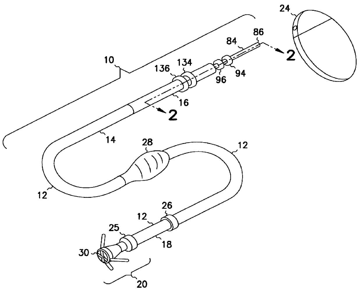
In the drawings described below, reference numerals are generally repeated where identical elements appear in more than one figure. Turning now to the drawings, and in particular to FIG. 1, there is shown an exemplary cardiac lead 10 that includes a flexible insulating sleeve 12 that has a proximal end 14 coupled to a connector 16, and a distal end 18 coupled to a tip electrode assembly 20. The connector 16 is designed to be inserted into a cardiac stimulator 24, and is shown highly exaggerated in size relative to the cardiac stimulator 24. The cardiac stimulator 24 may be a pacemaker, a cardioverter / defibrillator, or other type of stimulator or a sensing instrument. The tip electrode assembly 20 includes an annular member to aid in securing the sleeve 12 to the electrode assembly 20 as described more fully below. The illustrated embodiment of the lead 10 is bipolar. Accordingly, the distal end 18 is provided with an electrode 26 located proximal to the tip electrode assembly 20. Ho...


PUM


Abstract

A cardiac stimulator lead connector is provided. The connector includes a pin member that has a distal end and a first insulating sleeve coupled to the pin member. An annular member is coupled to the first insulating sleeve. A conductor sleeve is coupled to the annular member and a second insulating sleeve is coupled to the conductor sleeve. One or more conductor wires running from distal electrodes in a lead may be welded to the connector. The connector eliminates crimping as a mechanism to secure lead conductors to lead connectors.

Description

1. Field of the InventionThis invention relates generally to cardiac stimulator leads, and more particularly to a cardiac stimulator lead having a two-piece connector for connecting the lead to cardiac stimulator, such as a pacemaker or cardioverter / defibrillator.2. Description of the Related ArtConventional cardiac stimulator systems consist of a cardiac stimulator and an elongated flexible cardiac lead that is connected proximally to a header structure on the cardiac stimulator and is implanted distally at one or more sites within the heart requiring cardiac stimulation or sensing. The cardiac stimulator is normally a pacemaker, a cardioverter / defibrillator, a sensing instrument, or some combination of these devices.At the time of implantation, the distal end of a cardiac lead is inserted through an incision in the chest and manipulated by the physician to the site requiring electrical stimulation with the aid of a flexible stylet that is removed prior to closure. At the site requ...

Claims


Application Information

Patent Timeline
Patent Type & Authority Patents(United States)
IPC IPC(8): A61N1/05A61N1/375A61N1/372
CPCA61N1/056A61N1/3752
Inventor FISCHER, SR., ELMAR R.GERSTMANN, HANS
Owner INTERMEDICS
Why Eureka
Try Eureka