

Lever switch
- Summary
- Abstract
- Description
- Claims
- Application Information
AI Technical Summary
Benefits of technology
Problems solved by technology
Method used
Image

Examples
Embodiment Construction
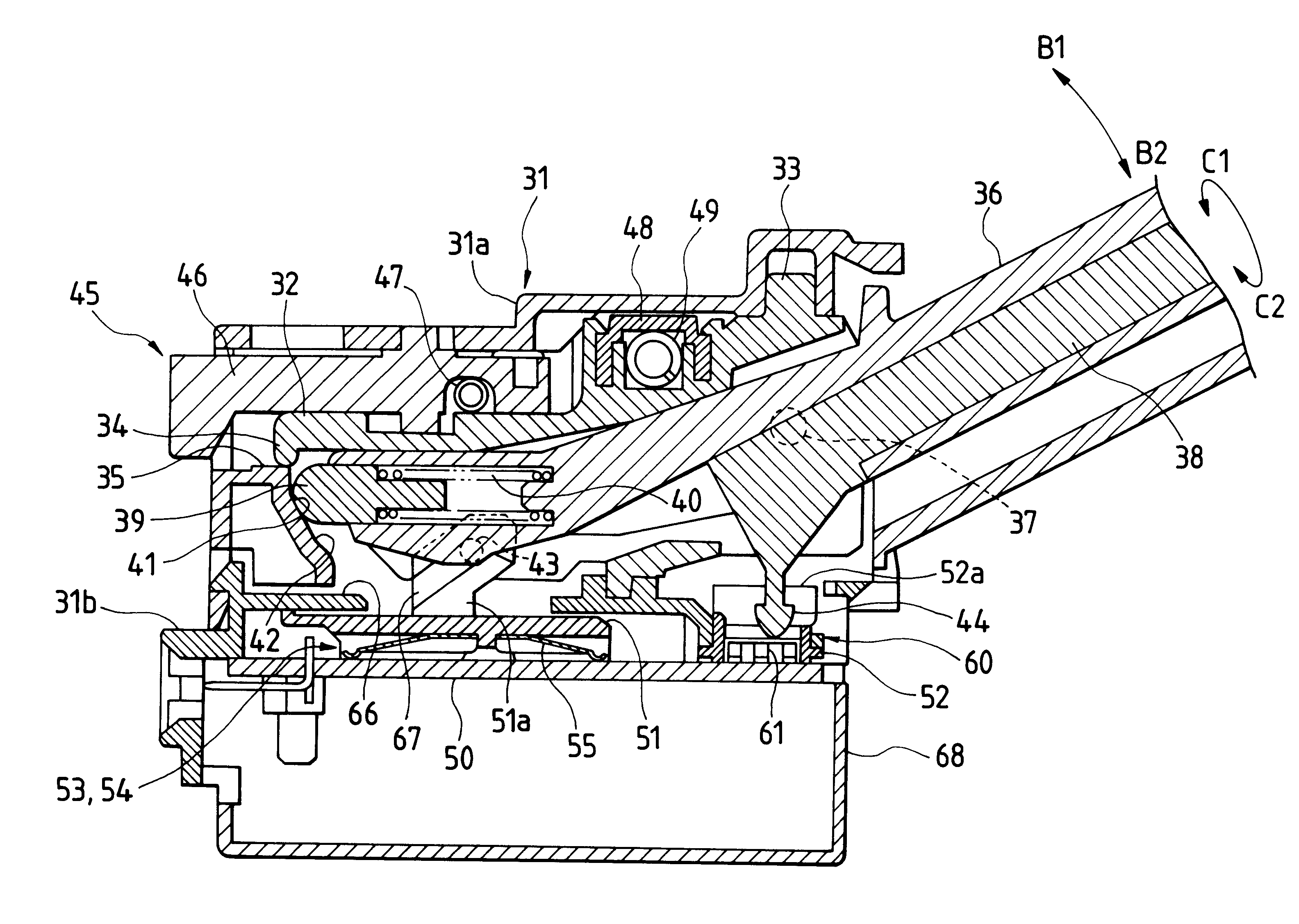
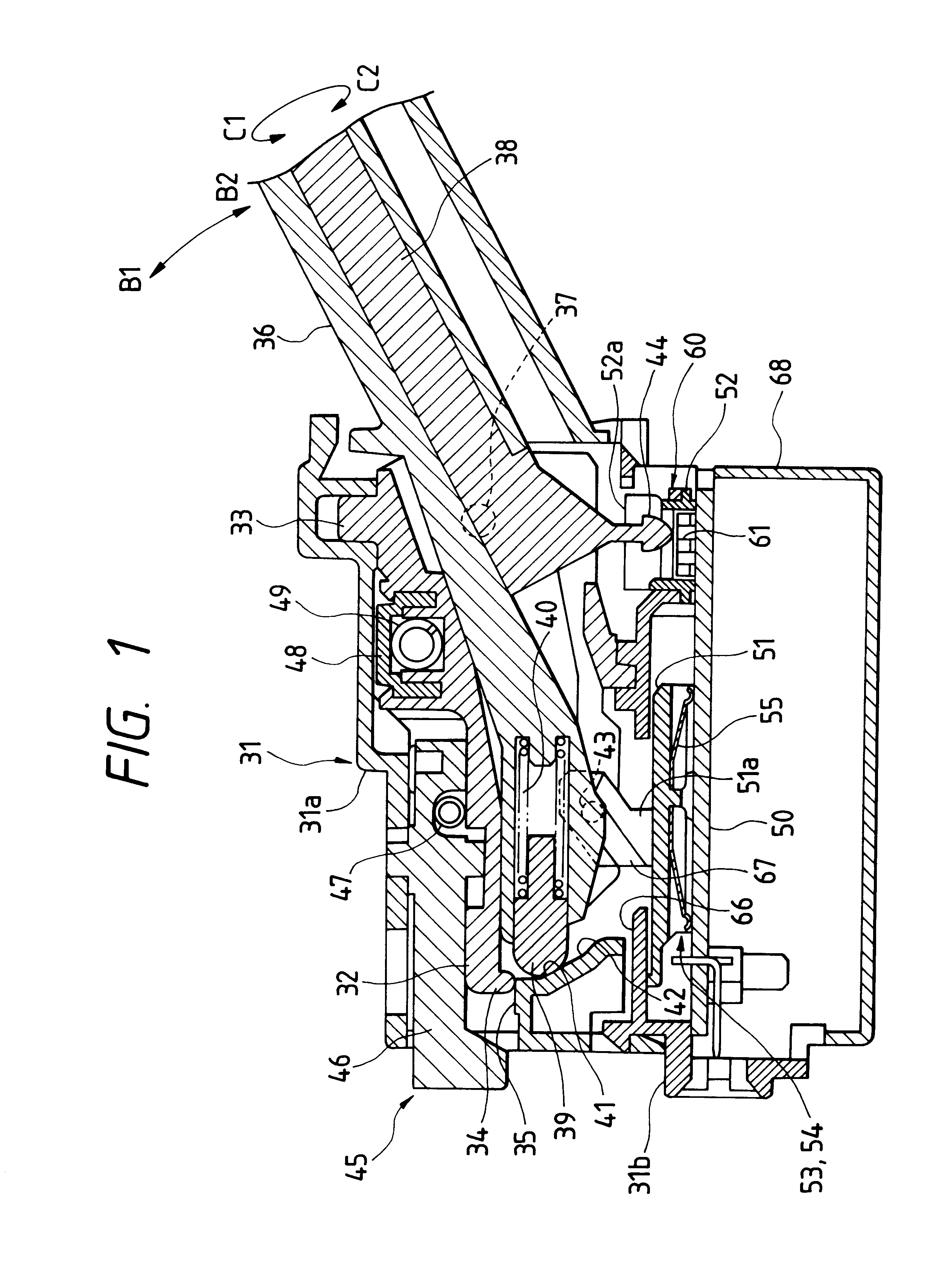
FIG. 1 is a sectional view of one embodiment of the present invention;
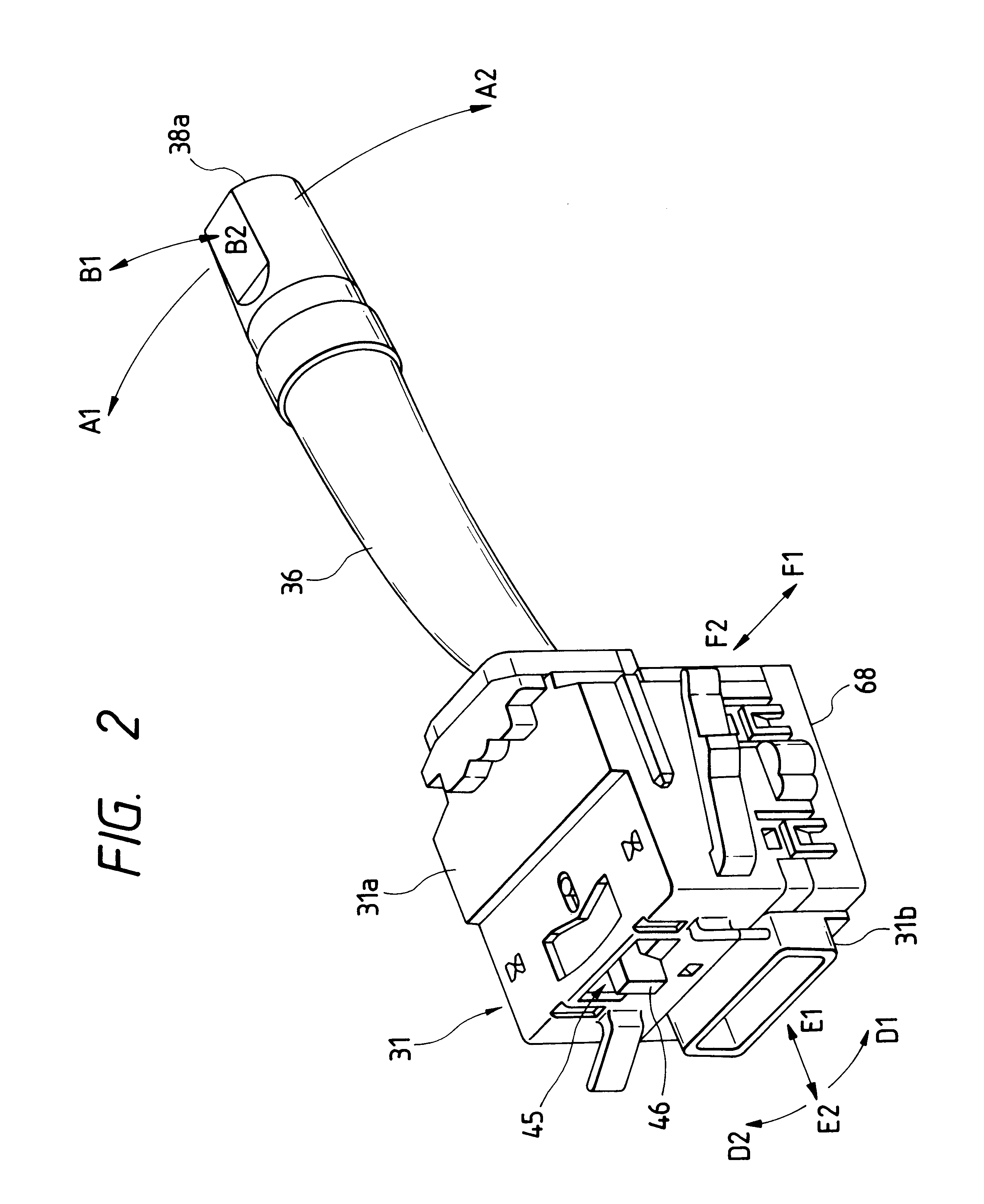
FIG. 2 is a perspective view showing an outer appearance of the same;
FIG. 3 is an exploded perspective view of the same;
FIG. 4 is an enlarged sectional view showing independently a first angle adjusting face in a direction of arrows A1, A2;
FIG. 5 is an enlarged sectional view showing independently a second angle adjusting face in a direction of arrows B1, B2;
FIG. 6 is a view corresponding to FIG. 1 showing a conventional structure;
FIG. 7 is a view of the same corresponding to FIG. 2;
FIG. 8 is a sectional view of the same while being assembled; and
FIG. 9 is a sectional view of the same in a state where a bracket is disengaged during assembling.
DETAILED DESCTIPTION OF PREFERRED EMBODIMENTS
Now, one embodiment of the invention applied to a lever switch assembly for a vehicle, especially an automobile will be described referring to FIGS. 1 to 5.
In FIGS. 1 to 3 is shown a case 31. The case 31 includes a first unit case ...
PUM
 Abstract
Description
Claims
Application Information