
Knitted foot cover and method of manufacture

a technology of foot cover and rim, which is applied in the direction of protective garments, textiles and paper, insoles, etc., can solve the problems of sewn-in rims bursting into the skin of the foot, high manufacturing cost, and high labor intensity

Inactive Publication Date: 2001-01-16
HIGHLAND MILLS
View PDF7 Cites 41 Cited by
  • Summary
  • Abstract
  • Description
  • Claims
  • Application Information

AI Technical Summary

Benefits of technology

The invention provides a pattern for making a shoe covering that can be easily made with standard knitting machines.

Problems solved by technology

The technical problem addressed in this patent is creating a more comfortable and easy-to-wear foot covering that does not require a lot of skill or cost. Previous versions were either too complicated to make or required specific materials like elastic yarns. The new design uses a simpler process to convert a standard knitted tube into a foot cover without adding extra material.

Method used


Image

  • Knitted foot cover and method of manufacture
  • Knitted foot cover and method of manufacture
  • Knitted foot cover and method of manufacture

Examples


example

The extra 5 courses in this band are to permit passing off of the blank form the needles.

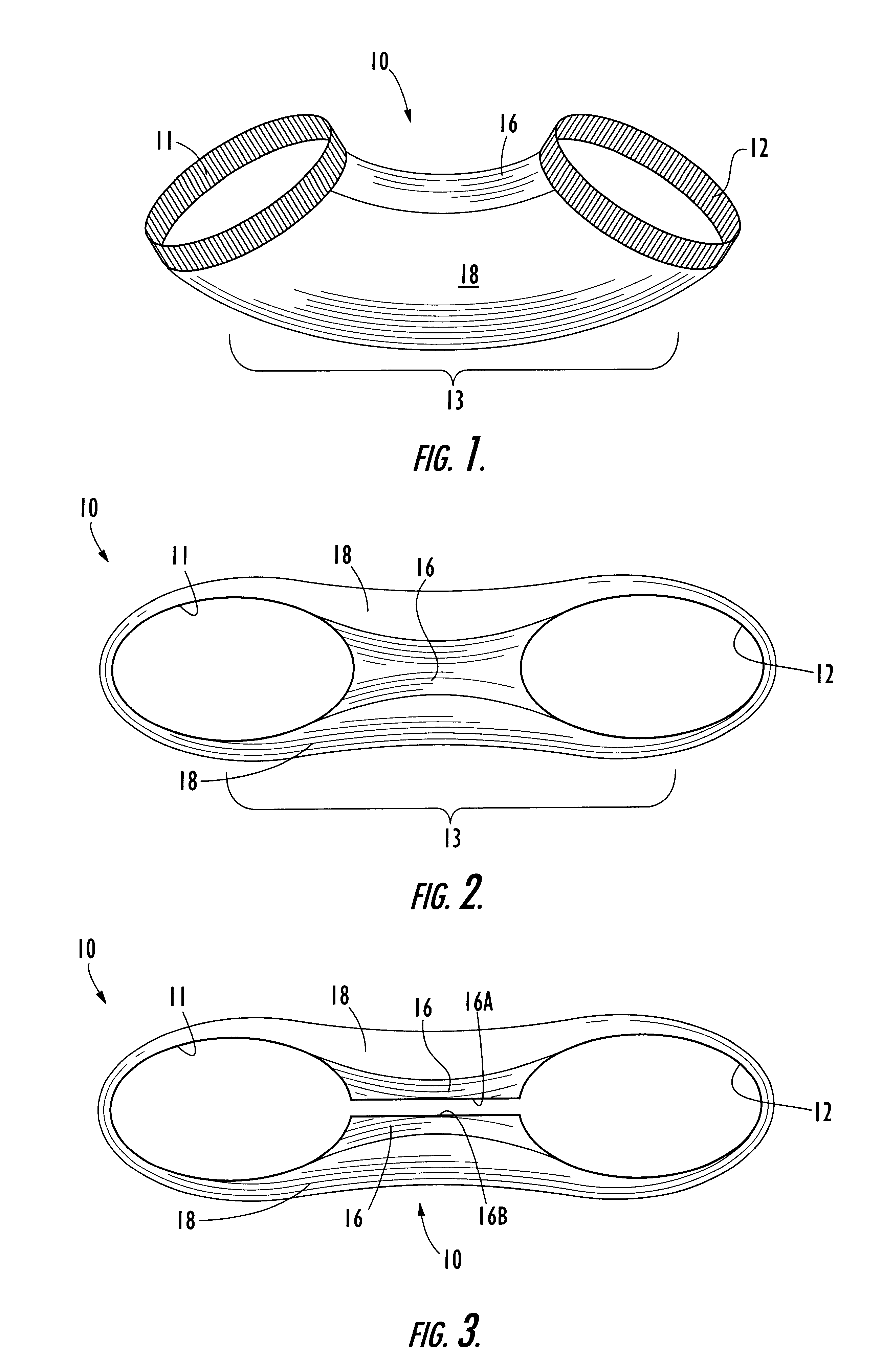
The alternating up-and-down needle arrangement in the construction of the panel creates the additional tension necessary to cause the panel 16 to be shorter than the panel 18. As noted above, this causes the blank 10 to assume a curved configuration desirable for completing the construction of the foot cover 30.

The body 13 is formed as follows:

The pattern repeats every 4 courses:

Fiber and yarn content according to the above example for both bands and body are as follows:

The blank 10 can also be made with a body 13 knitted of cotton yarn, for example, 80 singles cotton yarn, with the same Lycra / nylon content for the bands. Machines with diameters of 33 / 4 inches to 41 / 4 inches may be used, and other gauges, such as 288 needles.


PUM


Abstract

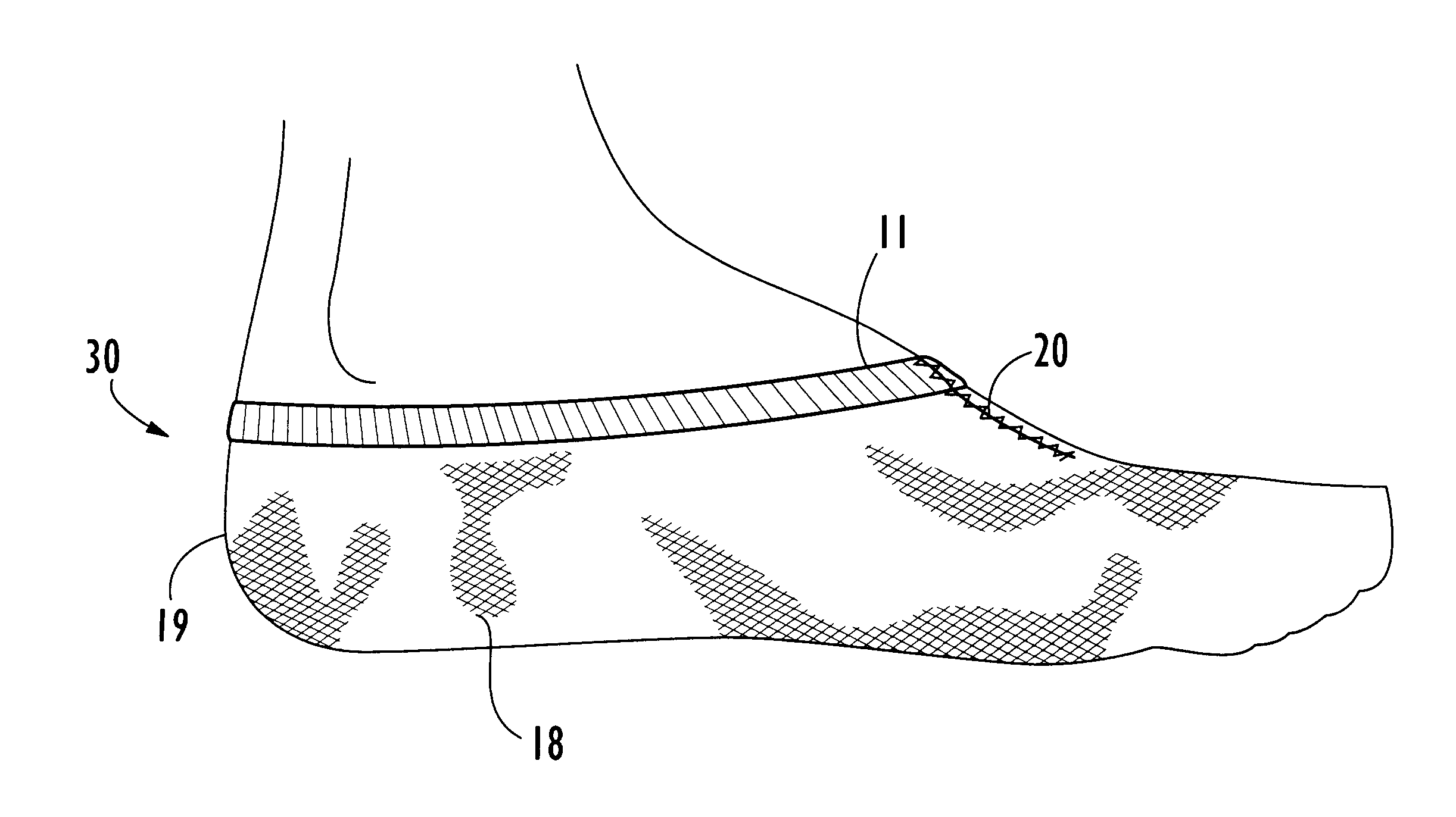
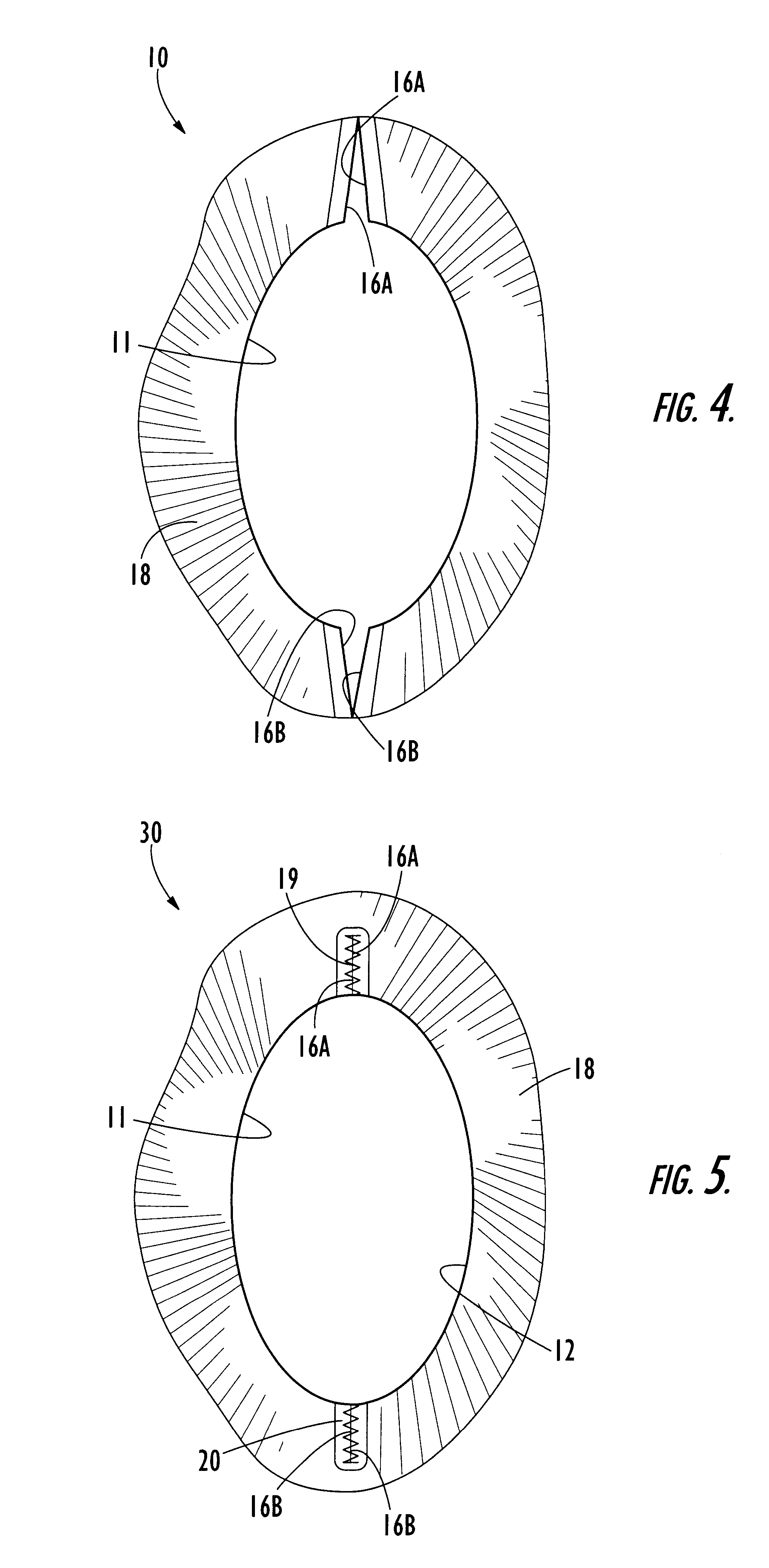
A tubular knitted body portion, first and second opposed band portions, each of the first and second band portions formed from a segment of respective tubular knitted band portions containing at least some elastic yarns. First and second seams close respective edges of the first and second opposed band portions to each other to define a single band having an elongated shape for being fitted in a stretched condition onto and hugging only the lower portion of the foot with the joined first and second bands positioned on the asymmetrical portion of the foot below the ankle. One of the seams extends along the top of the foot in substantial alignment with the longitudinal axis of the toes. The other of the seams extends along the back of the heel substantially along the longitudinal axis of the Achilles tendon.

Description


Claims


Application Information

Patent Timeline
Owner HIGHLAND MILLS
Learn More