Teatcup liner and a method of manufacturing a teatcup liner

Inactive Publication Date: 2001-01-23
DELAVAL HLDG AB
View PDF21 Cites 34 Cited by
  • Summary
  • Abstract
  • Description
  • Claims
  • Application Information

AI Technical Summary

Problems solved by technology

When the rubber material of such teatcup liners ages, the lip to enclose the teat will be weakened.
This means that the teatcup liner already at an initial stage, i.e. when it is applied to the teat, will crawl upwardly on the teat, which may result in a hindering influence to the milk flow.
Furthermore, a weakened lip means that the slip frequency, i.e. the inlet suction of air between the teatcup liner and the teat, increases.
Since the separate ring has to be mounted in the teatcup liner when this has been mounted in a teatcup shell, the exchange of the teatcup liner is complicated.
Furthermore, the ring provided

Method used


Image

  • Teatcup liner and a method of manufacturing a teatcup liner
  • Teatcup liner and a method of manufacturing a teatcup liner
  • Teatcup liner and a method of manufacturing a teatcup liner

Examples


Example

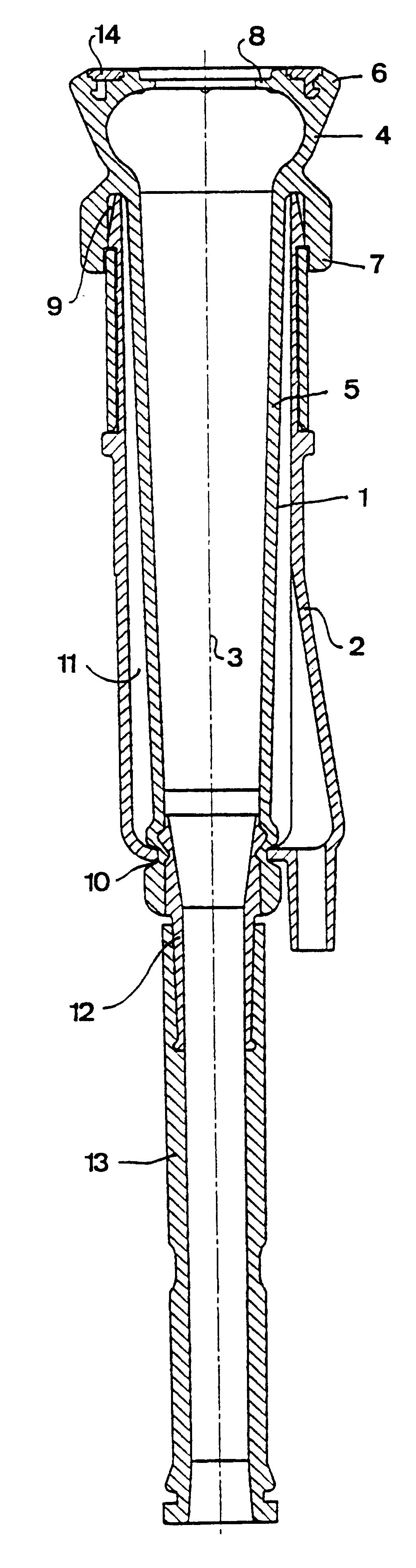
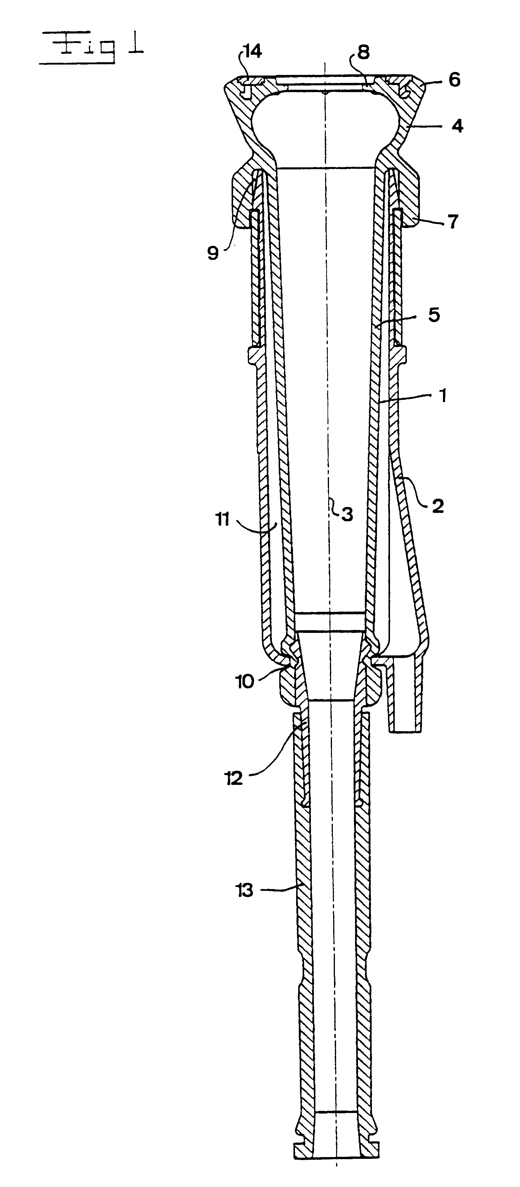
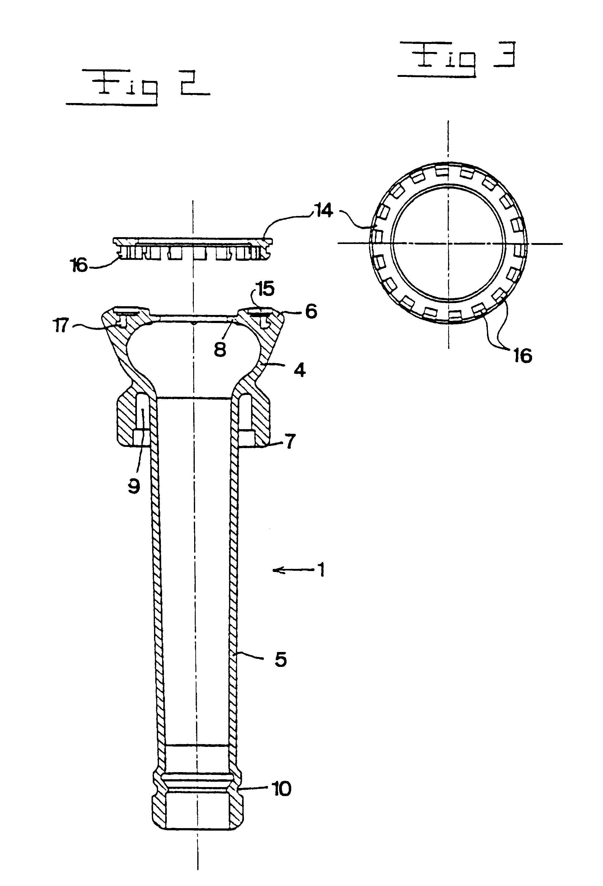
With reference to FIGS. 1-3, a teatcup is disclosed with a teatcup liner 1 which is provided in a teatcup shell 2. The teatcup liner 1 is essentially rotationally symmetrical with respect to a longitudinal axis 3 and comprises an upper tubular head portion 4 and a tubular shaft portion 5 extending downwardly from the head portion 4. The head portion 4 comprises a first upper end 6 and a second lower end 7. Beneath the upper end 6, the tubular head portion 4 comprises a lip 8 extending radially inwardly and defining an essentially circular central opening. The tubular head portion 4 forms a passage between the first end 6 and the second end 7 to the inner space of the teatcup liner for receiving a teat. The lower end 7 comprises an annular recess 9 which is engaged by the upper end portion of the teatcup shell 2. The lower part of the shaft portion 5 comprises a peripheral surrounding recess 10 which is engaged by the lower end portion of the teatcup shell 2. The recesses 9 and 10 ar...


PUM


Abstract

A teatcup liner (1) which is intended for being mounted in a teatcup shell (2) comprises a tubular head portion (4) forming a passage for receiving a teat. The passage extends between a first and a second axial end of the tubular head portion. The tubular head portion has an annular lip (8), which in the mounted as well as the non-mounted state of the teatcup liner (1) extends radially inwardly from the tubular head portion. Furthermore, the teatcup liner comprises a tubular shaft portion (5), which extends from a second axial end (7) of the head portion, and a member (14), which is arranged to provide a radially outwardly directed pretension in the lip in the mounted as well as the non-mounted state of the teatcup liner (1), and is located outside said passage. A method of manufacturing such a teatcup liner comprises the steps of moulding the teatcup liner, expanding the head portion, and providing the pretensioning member.

Description

1. Field of the InventionThe present invention refers to a teatcup liner intended for being mounted in a teatcup shell, comprisinga tubular head portion, which forms a passage arranged to receive a teat and extending between a first and a second axial end of the tubular head portion, and which comprises an annular lip, extending radially inwardly from the tubular head portion in the mounted as well as the non-mounted state of the teatcup liner,a tubular shaft portion, extending from the second axial end of the head portion, anda member arranged to provide a radially outwardly directed pretension in the lip in the mounted as well as the non-mounted state of the teatcup liner. Moreover, the invention refers to a method of manufacturing a teatcup liner.2.Description of the Prior ArtU.S. Pat. No. 4,324,201 discloses a type of teatcup liner which comprises a tubular upper part forming a passage for receiving a teat. An annular lip extends radially inwardly from the tubular upper part and...

Claims


Application Information

Patent Timeline
IPC IPC(8): A01J5/00A01J5/08
CPCA01J5/08
Inventor PETTERSON, TORBJORN KARL INGEMAR
Owner DELAVAL HLDG AB
Why Eureka
Try Eureka