Agricultural pneumatic tires having directional lugs

a technology of directional lugs and pneumatic tires, which is applied in the field of pneumatic tires, can solve the problems of affecting the comfort of driving on the general road, the fluidity of mud between the lugs becoming small, and the possibility of mud clogging

Inactive Publication Date: 2001-01-30
BRIDGESTONE CORP
View PDF15 Cites 40 Cited by
  • Summary
  • Abstract
  • Description
  • Claims
  • Application Information

AI Technical Summary

Benefits of technology

In general, as the lug forming angle .gamma. defined by an angle of a straight line connecting an end at the stepping-in side of the lug located near to a central portion of the tread to an end at the stepping-in side of the lug located near to each end of the tread with respect to a direction parallel to an axial direction of the tire becomes small, the traction component becomes large, but the fluidity of mud between the lugs is decreased and hence the mud clogging is apt to be caused. On the other hand, as the lug forming angle .gamma. becomes large, mud is easily fluidized between the lugs and the mud clogging is favorably prevented, but the distance from the end at the stepping-in side of the lug located near to the central portion of the tread to the end at the stepping-in side of the lug located near to each end of the tread or the lug length becomes long, so that it can not necessarily be said that the increase of the lug forming angle .gamma. is favorable in the prevention of the mud clogging.
The agricultural pneumatic tire according to the invention has the above construction, particularly a feature that the lug forming angle .gamma. defined by an angle of a straight line connecting an end at the stepping-in side of the lug located near to a central portion of the tread to an end at the stepping-in side of the lug located near to each end of the tread with respect to a direction parallel to an axial direction of the tire is 30-40.degree., so that the fluidity of mud between the lugs is easy and the mud clogging hardly occurs and the excellent traction performance is developed while matching with various soil conditions.
In the agricultural pneumatic tire according to the invention, the side wall at the stepping-in side of the lug is formed by a flat face slanted at the angle .alpha. of 30-45.degree. with respect to the face inclusive of the rotating axis of the tire in a region ranging from the outer surface of the lug to a position of the height h corresponding to 45-75% of the lug height H viewed at circumferential section perpendicular to the surface of the tread, whereby the traction performance is improved. And also, the bored face is formed in a region ranging from the end of the flat face having the inclination angle .alpha. toward a root of the lug, whereby the tilling performance is improved.
In the agricultural pneumatic tire according to the invention, the side wall at the kicking-out side of the lug is formed by a flat face slanted at the angle .beta.of 0-22.degree. with respect to the face inclusive of the rotating axis of the tire viewed at circumferential section perpendicular to the surface of the tread, whereby the traction performance is improved. When the angle .beta. exceeds 22.degree., the resistance in the running on soil undesirably increases to lower the driving force, while when it is less than 0.degree. or a minus value, the lug rigidity is small and the deformation in the running is large and hence the lug strength is insufficient and the traction performance is degraded.

Problems solved by technology

In order to decrease mud clogging on the muddy road, it is effective to widen a circumferential interval between the lugs arranged in the tread, but as the interval between the lugs becomes wider, ride comfortability against vibrations when the tire is run on general road are undesirably degraded.
On the other hand, as a lug forming angle or an angle of the lug inclined with respect to a direction parallel to an axial direction of the tire becomes small, the traction component becomes large, but the fluidity of mud between the lugs becomes small and the mud clogging is liable to be caused.
On the other hand, when the lug gets out from the soil during the running of the tire, there may be caused the carrying of soil.
Considering only the function when the lug enters into soil or gets out from soil, the side wall of the lug at the stepping-in side may be formed by the flat face having an inclination angle .alpha. of 30-45.degree. over a full lug height H. In this case, the space volume between the lugs becomes small and the carrying volume of soil becomes less to degrade the tilling performance, and also there may be caused an inconvenience of contacting the inclined faces of the adjacent side walls of the lugs with each other.
In order to avoid such a problem, the interval between the lugs is widened, which inversely causes the degradation of the ride comfortability against vibrations in the running on general road.
When the angle .beta. exceeds 22.degree., the resistance in the running on soil undesirably increases to lower the driving force, while when it is less than 0.degree. or a minus value, the lug rigidity is small and the deformation in the running is large and hence the lug strength is insufficient and the traction performance is degraded.
When the ratio L2 / L1 is less than 30%, the ride comfortability against vibrations extremely degrades, while when it exceeds 60%, it is difficult to adequately form the bored face and also top ends of the adjoining lugs located at the central portion of the tread extremely approach to each other and hence the soil clogging is apt to be caused.

Method used


Image

  • Agricultural pneumatic tires having directional lugs
  • Agricultural pneumatic tires having directional lugs

Examples


Embodiment Construction

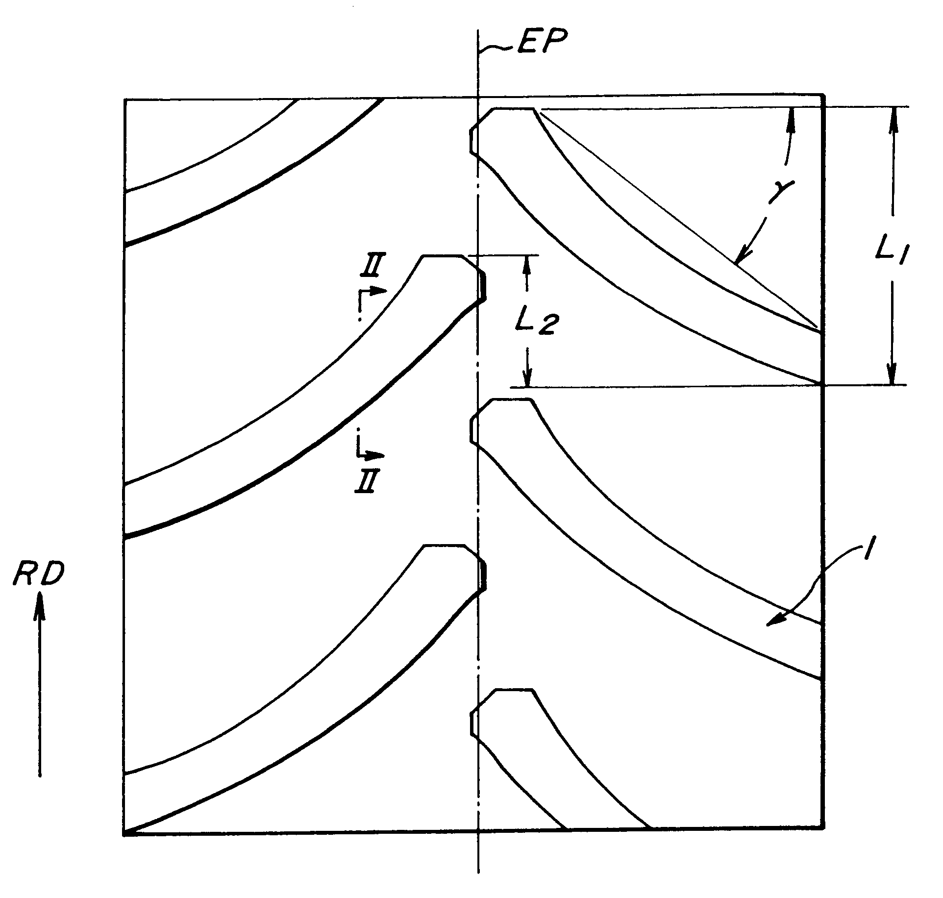
As shown in FIG. 1, an embodiment of the agricultural pneumatic tire according to the invention comprises a tread provided with many lugs 1 extending from a central portion of the tread toward both ends of the tread in a direction inclined with respect to a circumferential direction of the tire and alternately arranged right and left with respect to an equatorial plane EP of the tire at given intervals in the circumferential direction of the tire. These lugs 1 are directional slant lugs forming so-called directional tread pattern designating a rotating direction (forward running direction) RD when the tire is mounted onto a vehicle that an obliquely extended portion of the lug located at a side near to the equatorial plane EP first contacts with ground and the lug portion located far from the equatorial plane contacts with ground later.

A lug forming angle .gamma. defined by an angle of a straight line connecting an end at the stepping-in side of the lug 1 located near to the central...


PUM


Abstract

An agricultural pneumatic tire comprises a tread provided with many lugs extending at a given inclination angle from a central portion of the tread toward both ends of the tread and alternately arranged right and left with respect to an equatorial plane at given intervals in a circumferential direction of the tire, in which a side wall at a stepping-in side of the lug consists of a flat face slanted at a given angle with respect to a face perpendicular to the outer surface of the lug over a given distance from the outer surface and a bored face extending toward a root of the lug, and a side wall at a kicking-out side of the lug is a flat face slanted at a given angle with respect to the face perpendicular to the outer surface of the lug, and a ratio of circumferentially overlap component of the lug to circumferential length component is within a given range.

Description

1. Field of the InventionThis invention relates to a pneumatic tire, and more particularly to an agricultural pneumatic tire comprising a tread provided with many directional slant lugs extending from a central portion of the tread toward both ends of the tread in a direction inclined with respect to a circumferential direction of the tire and alternately arranged right and left with respect to an equatorial plane of the tire at given intervals in the circumferential direction of the tire.2. Description of Related ArtThere have hitherto been proposed and practiced many agricultural pneumatic tires each comprising a tread provided with many directional slant lugs extending from a central portion of the tread toward both ends of the tread in a direction inclined with respect to a circumferential direction of the tire and alternately arranged right and left with respect to an equatorial plane of the tire at given intervals in the circumferential direction of the tire in order to ensure...

Claims


Application Information

Patent Timeline
Patent Type & Authority Patents(United States)
IPC IPC(8): B60C11/03B60C11/11
CPCB60C11/0316B60C11/0311B60C2011/0313
Inventor SHIMIZU, NOBUO
Owner BRIDGESTONE CORP
Why Eureka
Try Eureka