Radial oscillating motor

a technology of radial oscillating motor and rotary piston, which is applied in the direction of rotary or oscillating piston engines, engine seals, electrical devices, etc., can solve the problems of limiting the application of rotary piston engines, adding to the cost, and disadvantageous to remove the overflow oil from rotary piston engines

Inactive Publication Date: 2001-01-30
ZF LEMFOEDER METALLWARE
View PDF8 Cites 29 Cited by
  • Summary
  • Abstract
  • Description
  • Claims
  • Application Information

AI Technical Summary

Problems solved by technology

Overflow lines of this type are technically required, but are implemented only reluctantly since technically complex devices and facilities are required which add to the cost.
Moreover, a great number of pipes are required which significantly limits the application of the oscillating motors because of the limitations imposed by the mounting conditions.
In certain applications, it is disadvantageous to remove the overflow oil from the oscillating motor, for example, when the control system for the oscillating motor is malfunctioning and the rotor has to be kept in a fixed position.
Leakage typically causes the rotor to yield to an externally applied load which may pose a safety risk.

Method used


Image

  • Radial oscillating motor
  • Radial oscillating motor
  • Radial oscillating motor

Examples


first embodiment

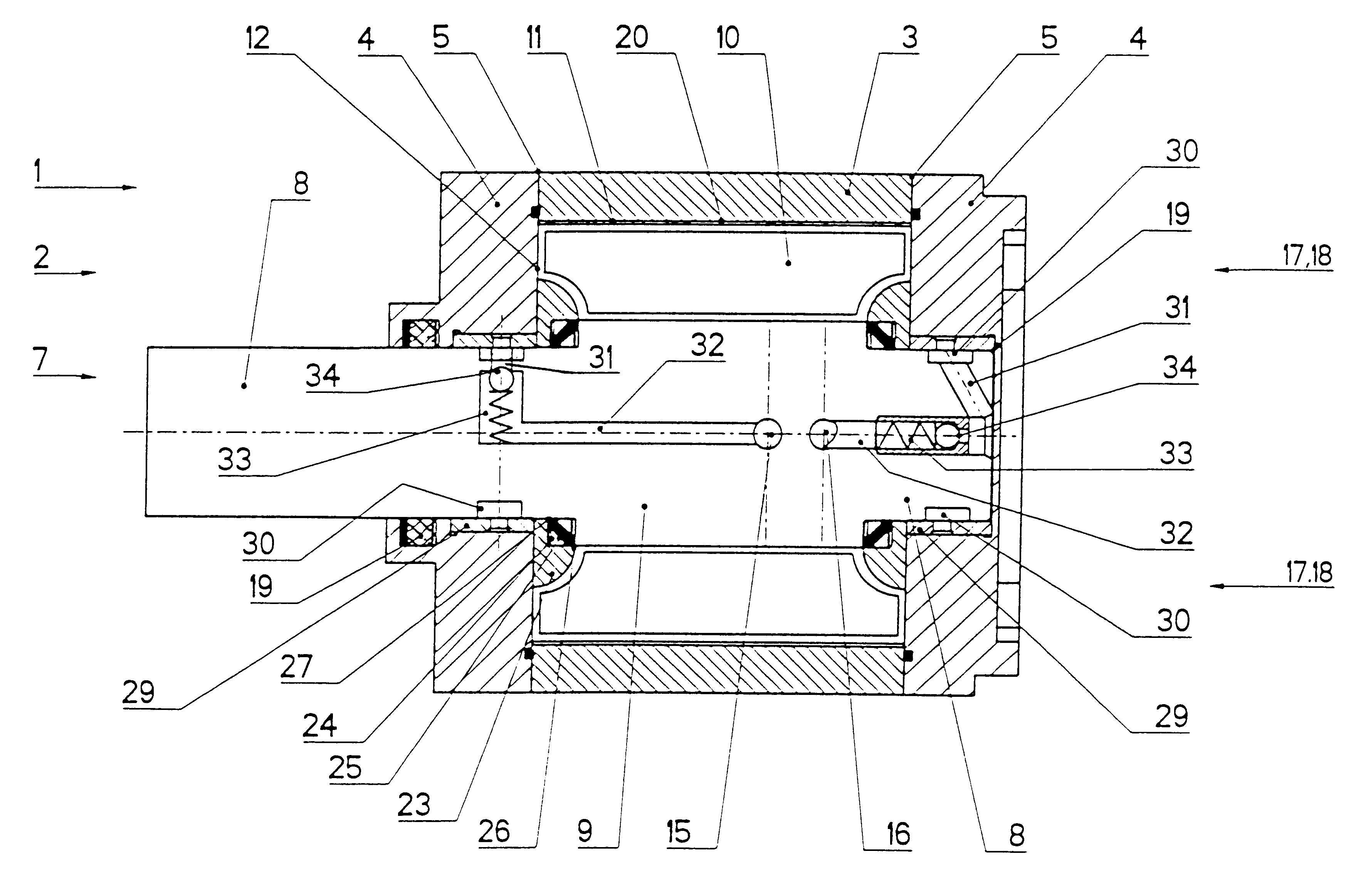
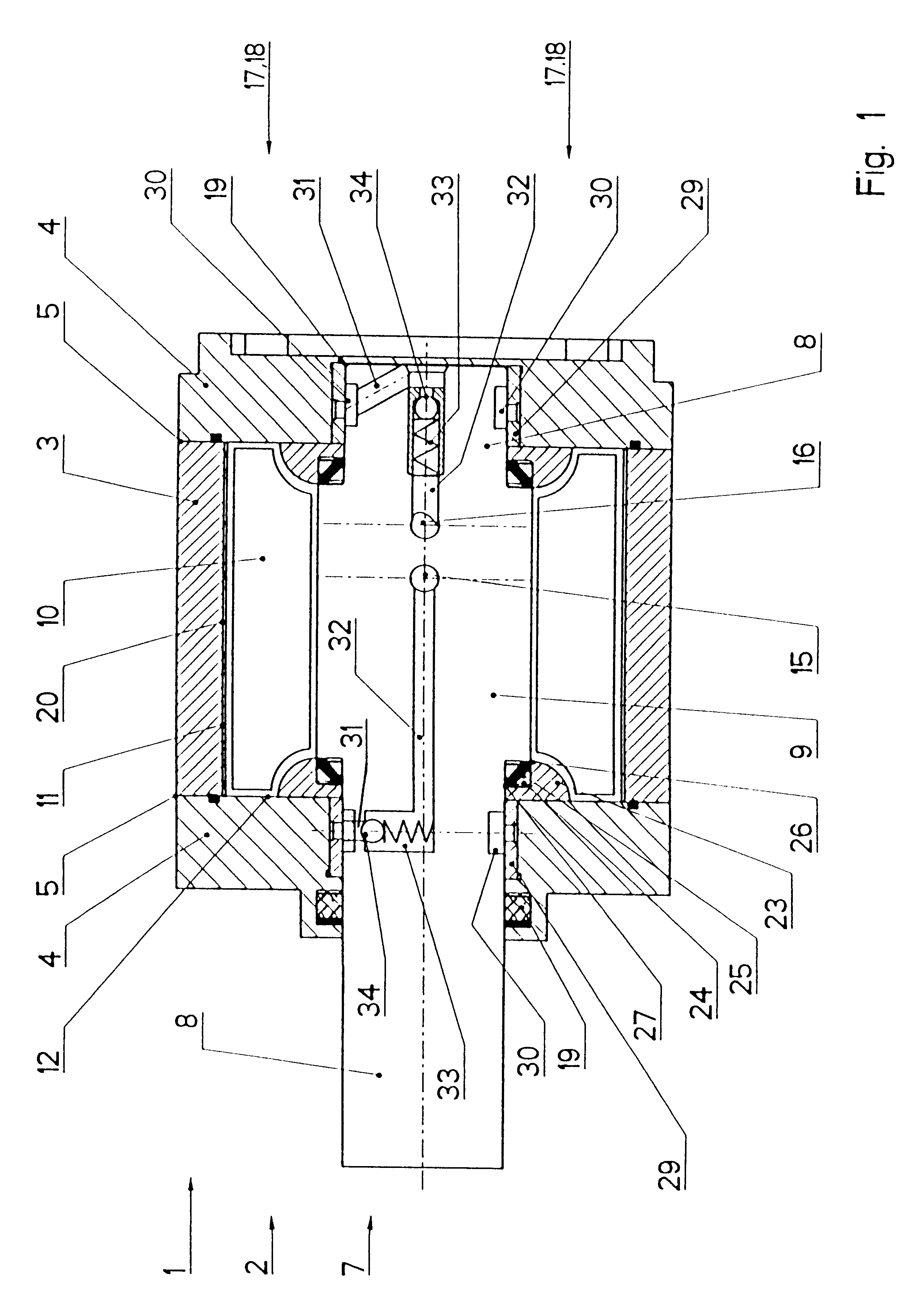
In a first embodiment, a connection is established through a radial duct 301 and an axial duct 32 to one of the ducts 15 or 16 which connect, as discussed above, the respective pressure chambers 13 or discharge chambers 14, respectively. The radial channel 31 or the axial channel 32 include a mounting space 33 for a non-return valve 34. This non-return valve 34 is spring loaded and closes towards the bearing 29.

With this arrangement, each bearing 29 is connected with one of the two ducts 15 or 16 which connect the two pressure chambers or discharge chambers 13 and 14.

Alternatively, the two bearings 29 can be associated with a common connecting duct which receives a common non-return valve 34 and is connected with one of the two ducts 15 or 16.

second embodiment

In a second embodiment, the two annular main ducts 30 are connected with each other through a radial collecting duct 35 and a common axial duct 36. The axial duct 36 is connected, on one hand, through a radial duct 37 with one of the two pressure chambers 13 and, on the other hand, through a radial duct 38 with one of the two discharge chambers 14. A respective non-return valve 39 and 40 is disposed in the radial duct 37 as well as in the radial duct 38. Both non-return valves 39, 40 are oriented so as to open towards the respective discharge chamber 14.

During the operation of the oscillating motor, a pressure medium consisting of oil leaked from the pressure chamber 13 reaches the region of the bearing 29 via the axial sealing gap formed between the sliding sealing ring 23 and the cylinder portion 9 of the rotor 2. The leaked oil accumulates at this location since the oil cannot drain freely via the annular sealing element 19.

In the first embodiment, the first non-return valve 34 o...


PUM


Abstract

Radial oscillating motors are generally fitted with an outer overflow oil line in order to protect sealing elements. This requires an over large amount of devices and system expenditure. Large amounts of installation space are also required for oscillating motors of this kind. The invention provides a radial oscillating motor wherein each bearing (29) is hydraulically connected to a discharge chamber (14) via a main duct (30) in addition to radial ducts (31, 15, 16, 35, 37, 38) and axial ducts (32, 36) in a driven shaft (7). A non-return valve opening out in the direction of the discharge chamber (14) is inserted into the ducts (31, 32, 37, 38).

Description

1. Field of the InventionThe invention relates to a radial oscillating motor having a stator in a housing, a stator wing being disposed in the housing. A rotor having a driven shaft is supported in the housing and associated therewith is an identical number of rotor wings. The stator wing and the rotor wing in conjunction with the housing, the cylinder portion of the drive shaft and the two covers form a pressure chamber and one discharge chamber, which are sealed towards the inside by a frame sealing element which is inserted in the stator wing and the rotor wing, and which are sealed towards the outside and the inside by an annular sealing element. Further, a bearing, which has a pressure relief, is disposed in each cover of the stator between two sealing locations.Such oscillating motors are used in particular in the aircraft and vehicle industry.2. Description of the Related ArtDE 32 22 982 A1 describes a radial oscillating motor consisting of, for example, a housing, which has ...

Claims


Application Information

Patent Timeline
Patent Type & Authority Patents(United States)
IPC IPC(8): F15B15/00F15B15/12F15B15/14
CPCF15B15/12F15B15/149
Inventor REICHEL, KLAUSBEETZ, STEFAN
Owner ZF LEMFOEDER METALLWARE
Why Eureka
Try Eureka