Thin battery

a thin battery, light weight technology, applied in the direction of batteries, primary cell maintenance/servicing, non-aqueous electrolyte cells, etc., can solve the problems of affecting the operation of the battery, the inner pressure of the sealed portion rises, and the battery is not equipped with a safety mechanism for blocking current passage,

Inactive Publication Date: 2001-02-13
MITSUBISHI ELECTRIC CORP
View PDF12 Cites 54 Cited by
  • Summary
  • Abstract
  • Description
  • Claims
  • Application Information

AI Technical Summary

Problems solved by technology

However, this battery is not equipped with a safety mechanism for blocking current passage upon the occurrence of troubles such as overcharging and shortcircuiting or relaxing the inner pressure of the encapsulating bag 6.
In general, when gas is produced from the electrolyte or active material due to overcharging or shortcircuiting in a sealed battery encapsulating a battery body, the

Method used


Image

  • Thin battery
  • Thin battery
  • Thin battery

Examples


embodiment 1

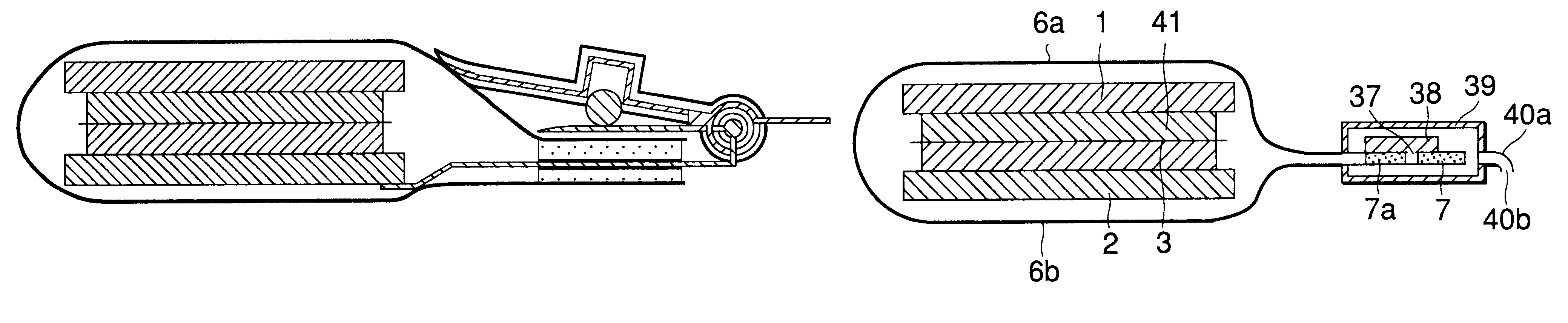
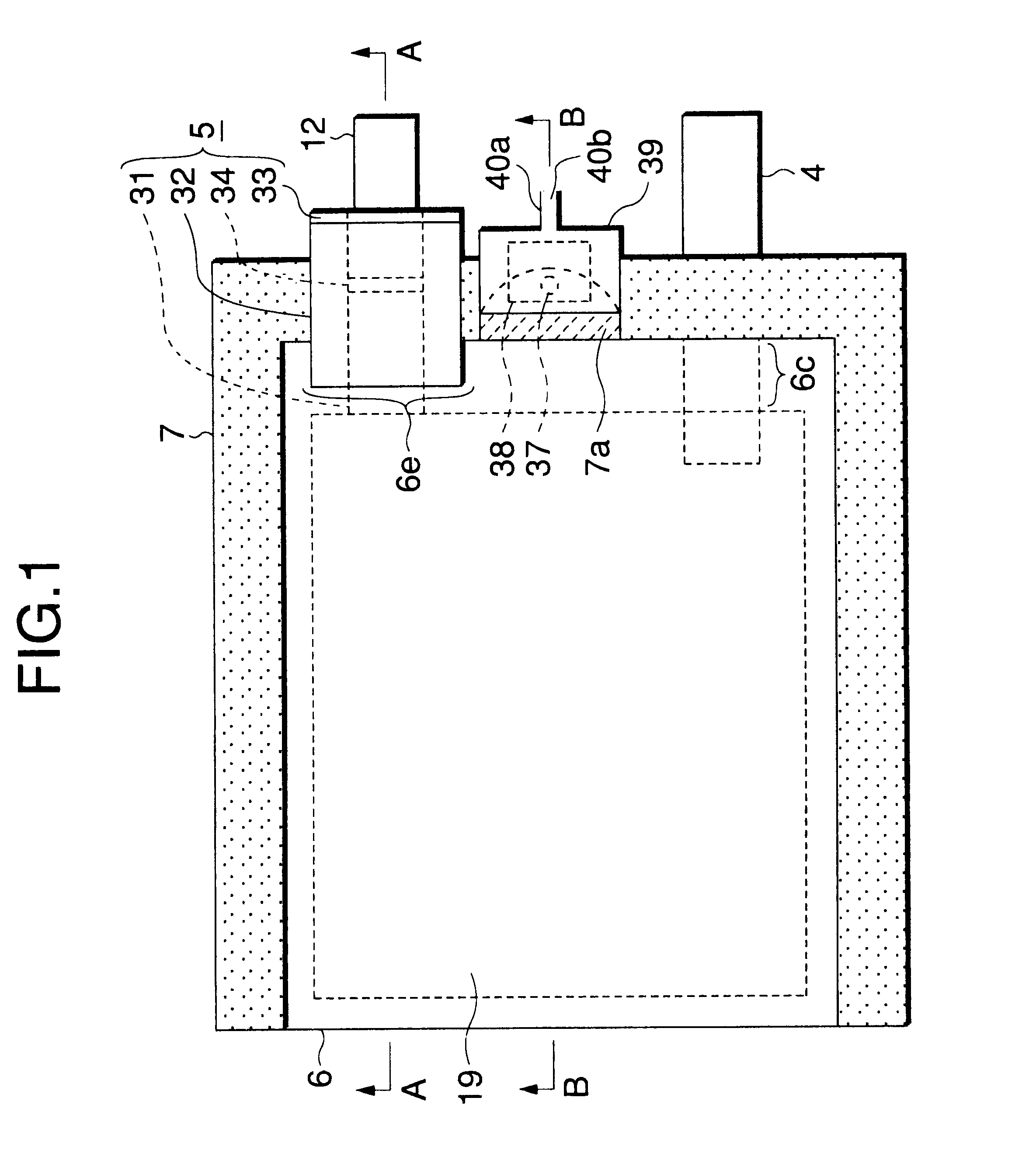
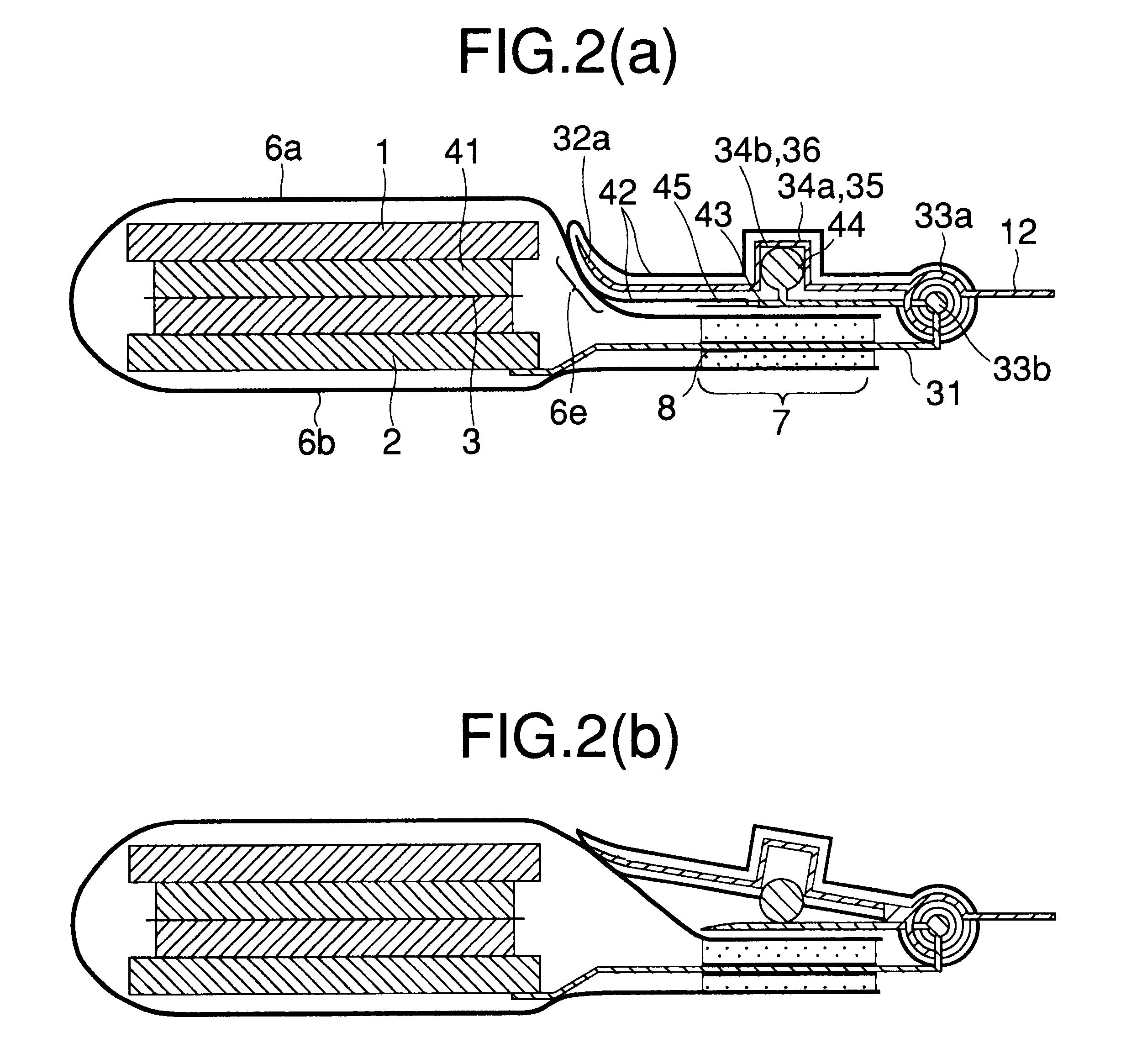
A thin battery according to Embodiment 1 of the present invention will be described in connection with the drawings. FIG. 1 is an entire schematic diagram as viewed from the top of a thin secondary battery equipped with a safety device according to Embodiment 1 of the present invention. FIG. 2 is a sectional view taken on line A--A of FIG. 1. FIG. 2(a) illustrates how the battery works during normal charging / discharging. FIG. 2(b) illustrates how the collector tab acts to block current passage when the inner pressure of the flexible encapsulating bag rises. In these drawings, the reference numerals 1 and 2 indicate a positive electrode and a negative electrode, respectively. The reference numerals 3 and 41 indicate a separator and an electrolyte layer, respectively. The separator 3 and the electrolyte 41 together form an ionically-conducting layer. The electrolyte 41 is any one of solid state, gel state electrolyte and material impregnated by liquid electrolyte. The reference numera...

embodiment 2

FIG. 4 concerns Embodiment 2 of the present invention and is a perspective view illustrating another embodiment of the collector tab with a current blocking function. While the groove 35 and rod 36 constituting the joint portion 34 is parallel to the hinge portion 33 in FIG. 2, the groove 35 and rod 36 are perpendicular to the hinge portion 33 in FIG. 4. The other basic structure of the embodiment of FIG. 4 is the same as that of FIG. 2 and thus will not be described herein.

embodiment 3

FIG. 5 concerns Embodiment 3 of the present invention and illustrates a further embodiment of the collector tab with a current blocking function. FIG. 5(a) is a diagram as viewed from the top of the collector tab with a current blocking function according to Embodiment 3 of the present invention. FIG. 5(b) is a sectional view taken on line A--A of FIG. 5(a) illustrating how the battery works during normal charging / discharging. FIG. 5(c) is a sectional view taken on line A--A of FIG. 5(a) illustrating how the collector tab acts to block current passage when the inner pressure of the encapsulating bag rises beyond the first predetermined value. In these drawings, the reference numeral 51 indicates a dislocation stop pin, the reference numeral 51a indicates a pin rod, the reference numeral 51b indicates a pin ball, and the reference numeral 52 indicates a dislocation stop round hole. While the joint 34 composed of the groove 35 and the rod 36 and the hinge 33 are used as fastening mean...


PUM

PropertyMeasurementUnit
Massaaaaaaaaaa
Massaaaaaaaaaa
Specific weightaaaaaaaaaa

Abstract

A thin battery includes a flat battery body having a positive electrode and a negative electrode having an electrolyte layer disposed between the electrodes. A flexible encapsulating bag seals the battery body with a sealing portion. A positive electrode collector tab and a negative electrode collector tab are respectively connected to the positive and negative electrodes. The tabs penetrate the encapsulating bag. At least one of the tabs includes first and second collector tabs and a safety device so that an electrical connection between the first and second collector tabs may be interrupted when the internal pressure of the encapsulating bag exceeds a predetermined value.

Description

1. Field of the InventionThe present invention relates to a light weight small-sized thin battery to be mounted in portable electronic apparatus. The present invention relates to, e.g., lithium ion secondary battery which needs to be sealed so that it is free of water content, particularly a thin battery comprising a safety mechanism which can work when the battery body is simply sealed in the form of bag.2. Description of the Related ArtFIG. 30 illustrates a schematic diagram of a prior art thin secondary battery disclosed in publications (e.g., "Kouseino Denchi no saishin manyuaru (Modern manual of high performance battery)", Sogo Gijutsu Center, page 185, 1989). In this drawing, the reference numeral 1 indicates a positive electrode, the reference numeral 2 indicates a negative electrode, the reference numeral 3 indicates a separator, the reference numeral 4 indicates a positive electrode collector tab, the reference numeral 5 indicates a negative electrode collector tab, the ref...

Claims


Application Information

Patent Timeline
IPC IPC(8): H01M2/02H01M2/34H01M2/12H01M10/04H01M2/20H01M6/00H01M6/40H01M6/18H01M6/50H01M50/119H01M50/121H01M50/129H01M50/133H01M50/55H01M50/557H01M50/583
CPCH01M2/0212H01M2/0275H01M2/12H01M2/34H01M2/345H01M2/348H01M10/0431H01M6/181H01M6/40H01M2200/101Y02E60/10H01M50/557H01M50/30H01M50/578H01M50/581Y02P70/50H01M50/583H01M50/133H01M50/121H01M50/129H01M50/55H01M50/119H01M50/20
Inventor SHIOTA, HISASHIYOKOYAMA, TETSUHIDEAIHARA, SHIGERUSHIRAGA, SYO
Owner MITSUBISHI ELECTRIC CORP
Why Eureka
Try Eureka