
Fuel transfer and conditioning unit for automotive vehicle

a technology for automotive vehicles and fuel systems, applied in the direction of machines/engines, separation processes, filtration separation, etc., can solve the problem of contaminating the fuel system downstream of the pump with impurities

Inactive Publication Date: 2001-02-20
FORD GLOBAL TECH LLC
View PDF44 Cites 42 Cited by
  • Summary
  • Abstract
  • Description
  • Claims
  • Application Information

AI Technical Summary

Problems solved by technology

A problem with the unit disclosed in the '822 patent resides in the fact that if the filter element is removed, the unit may nevertheless be used to transfer fuel, giving rise to the possibility of contaminating the fuel system downstream of the pump with impurities which are drawn and passed through the transfer pump in the absence of a filter.

Method used


Image

  • Fuel transfer and conditioning unit for automotive vehicle
  • Fuel transfer and conditioning unit for automotive vehicle
  • Fuel transfer and conditioning unit for automotive vehicle

Examples


Embodiment Construction

)

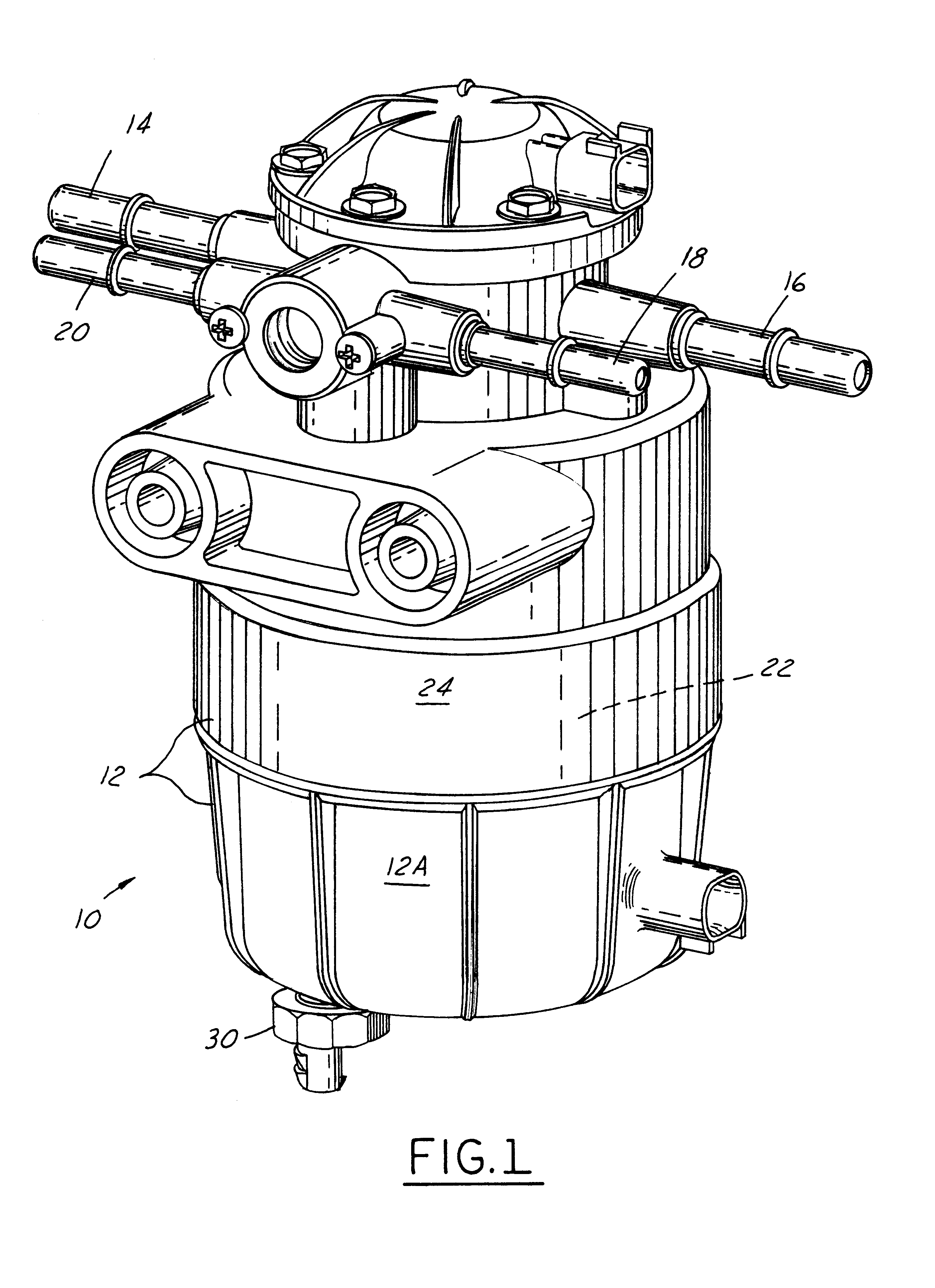
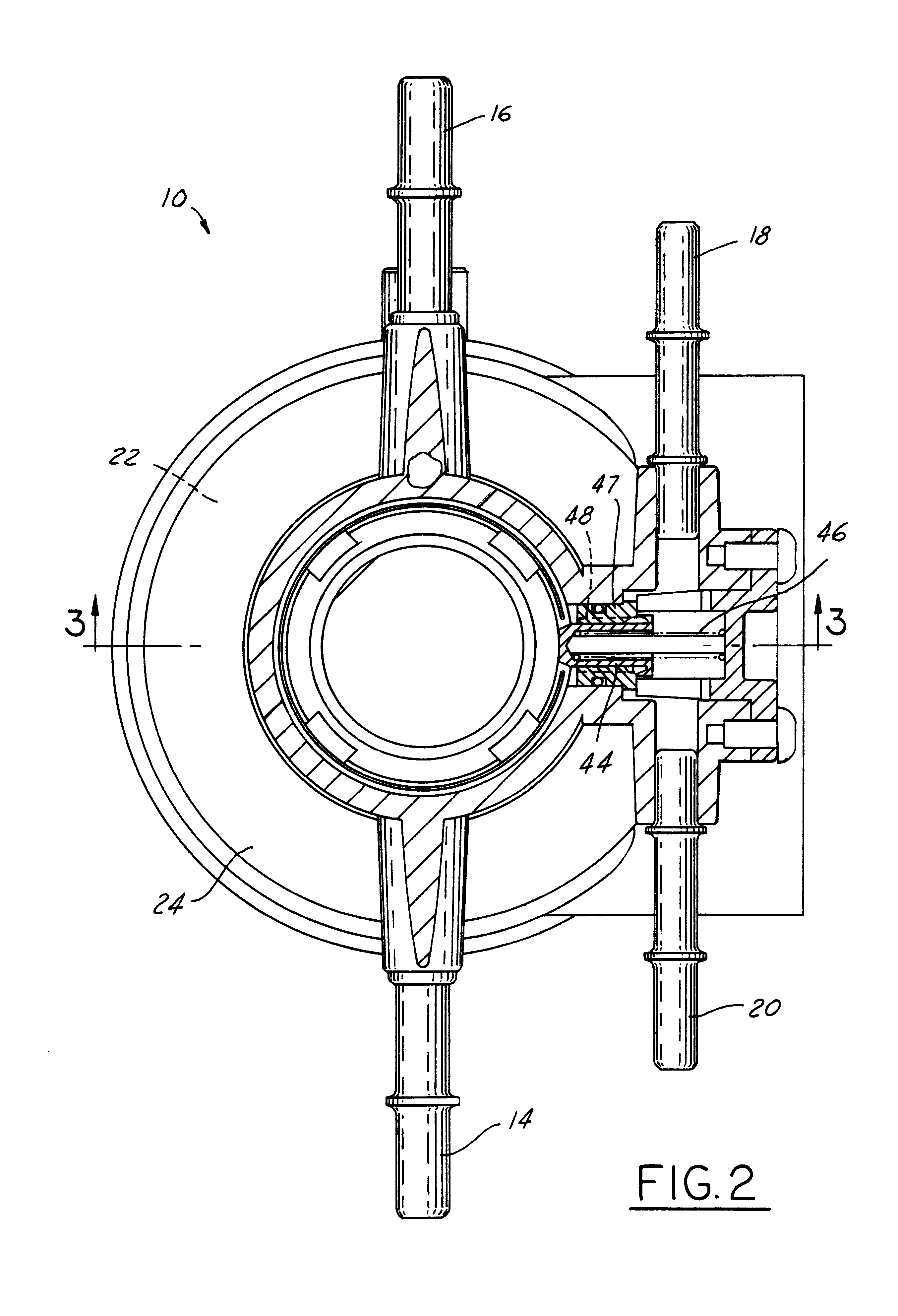
As shown in FIG. 1, fuel transfer and conditioning unit 10 has reservoir 12 consisting of a lower bowl 12A with the upper part of the reservoir being formed in housing 24. As explained above, fuel enters unit 10 through tank supply 14 and flows to the engine via engine supply port 16. Fuel returns from the engine (not shown) through engine return port 18 and flows from unit 10 via fuel tank return port 20. Drain 30 allows any water which has accumulated within reservoir 12 to be eliminated.

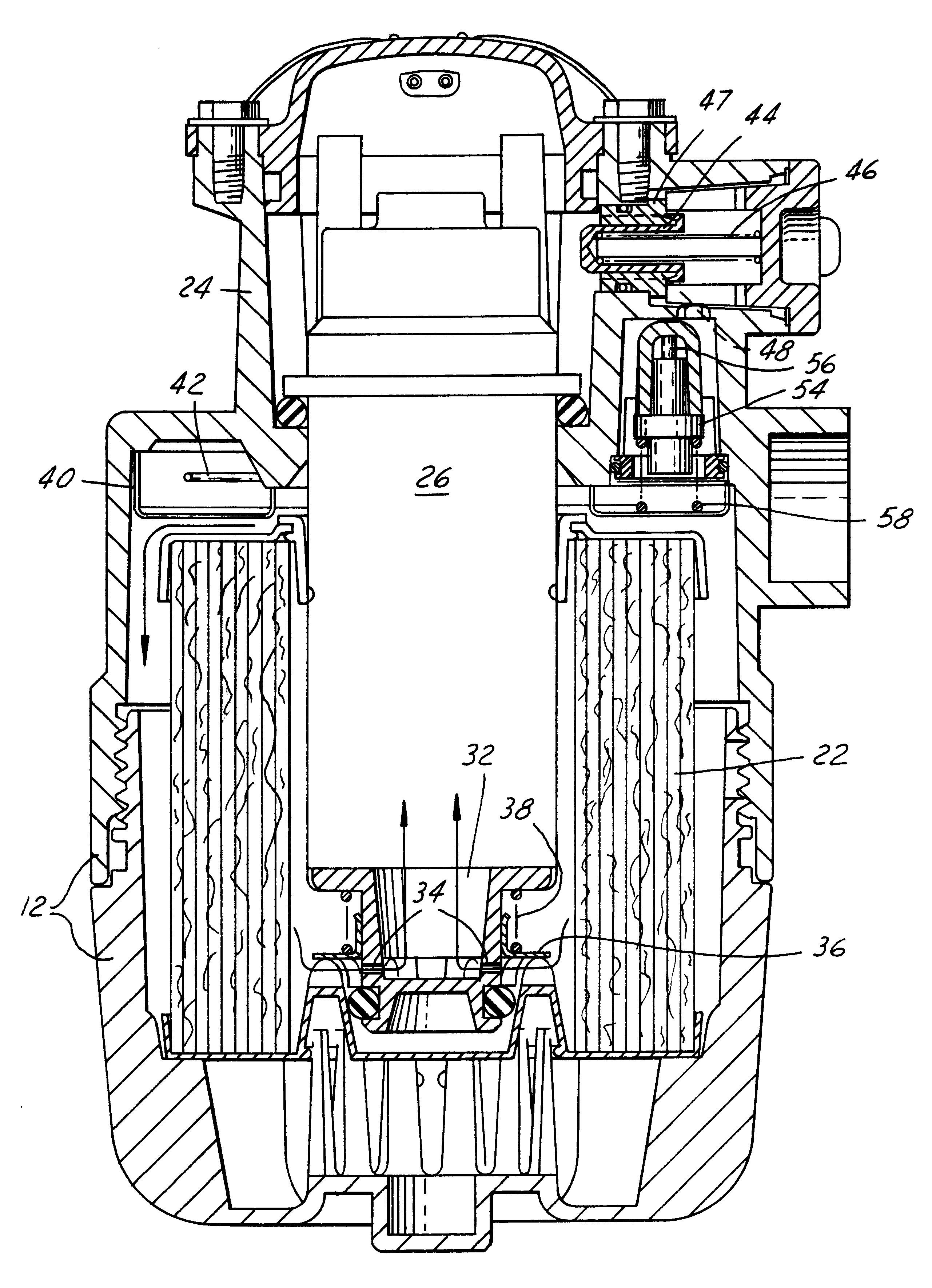
FIGS. 2 and 3 illustrate with particularity the pressure control function of the present unit. The purpose of the pressure control function is to limit the pressure of the fuel supplied to an engine. This function is achieved by means of fuel pressure control plunger 44 which is mounted within valve body 47. As shown in FIG. 3, fuel flowing through electric pump 26 or, for that matter, through the hand pump shown in FIG. 4, flows from the interior of unit 10 through a series of axial passages 48 ...


PUM

PropertyMeasurementUnit
Temperatureaaaaaaaaaa
Pressureaaaaaaaaaa

Abstract

A fuel transfer and conditioning unit for an automotive vehicle includes a reservoir with a generally cylindrical filter element and a pump module contained within the reservoir and extending within the filter element. A combination valve prevents forward flow of fuel through the pump module unless the filter element is installed within the reservoir and also prevents reverse flow of fuel from the engine in the event the filter element is removed for maintenance.

Description

1. Field of the InventionThe present invention relates to fuel conditioning for the purpose of supplying fuel to an internal combustion engine.2. Background InformationCombination fuel pump and filter units which are mounted remotely from a vehicle fuel tank are known in the art. U.S. Pat. No. 5,036,822 discloses such a unit intended for use in a watercraft. A problem with the unit disclosed in the '822 patent resides in the fact that if the filter element is removed, the unit may nevertheless be used to transfer fuel, giving rise to the possibility of contaminating the fuel system downstream of the pump with impurities which are drawn and passed through the transfer pump in the absence of a filter. A fuel transfer and conditioning unit according to the present invention solves this problem by preventing the transfer of fuel if the filter is not installed in the unit.A fuel transfer and conditioning unit for supplying liquid fuel to an internal combustion engine of an automotive veh...

Claims


Application Information

Patent Timeline
IPC IPC(8): B01D29/15B01D29/13B01D35/153B01D35/14F02M37/04F02M37/22F02M37/14F02M37/30F02M37/42F02M37/44F02M37/46F02M37/48
CPCB01D29/15B01D35/147B01D35/153F02M37/14F02M37/22B01D29/608B01D29/96B01D35/157B01D35/26B60K2015/03105F02M37/42F02M37/48F02M37/30F02M37/44F02M37/46
Inventor BROWN, BRADLEY ALLENARMESTO, CARLOS
Owner FORD GLOBAL TECH LLC
Features
  • Generate Ideas
  • Intellectual Property
  • Life Sciences
  • Materials
  • Tech Scout
  • Unparalleled Data Quality
  • Higher Quality Content
  • 60% Fewer Hallucinations
Learn More