Selectively lockable needle guard

a needle guard and lockable technology, applied in the field of medical devices, can solve the problems of contaminated needle shield replacement, user extreme care, waste of syringe, etc., and achieve the effects of convenient use, convenient construction, and convenient manufacturing

Inactive Publication Date: 2001-02-20
GETTIG TECH
View PDF74 Cites 42 Cited by
  • Summary
  • Abstract
  • Description
  • Claims
  • Application Information

AI Technical Summary

Benefits of technology

There is a further need for a needle guard having the above-mentioned attributes that can be economically manufactured and is easy and safe to use.
It is a feature of the present invention to provide a guard for a hypodermic needle that can be releasably latched in a needle-guarding position between injections and that also has the capability of being permanently locked in such position to render the needle unusable for further injections and for safe disposal thereof.
It is another feature of the present invention to provide a needle guard having the above-mentioned attributes that can be economically manufactured and easy to use.
It is still another feature of the present invention to provide a needle guard assembly that has the above-mentioned attributes and that can be readily constructed for use with a variety of syringe arrangements.

Problems solved by technology

Replacement of the shield on the contaminated needle was fraught with risk and required extreme care on the user's part to avoid inadvertent sticks by the contaminated needle.
Furthermore, if the user lost or misplaced the shield during the injection process or otherwise failed to replace it after use, the syringe was disposed of with an exposed contaminated needle.
While many of such inventions effectively addressed the problems of inadvertent needle sticks, such inventions were often difficult to economically fabricate and / or difficult to use.
Thus, they were not readily embraced by the healthcare community.
For example, many of such guards are slidably supported on the syringe, but lack a mechanism for retaining the needle guard in its extended position wherein it fully protects the needle.

Method used


Image

  • Selectively lockable needle guard
  • Selectively lockable needle guard
  • Selectively lockable needle guard

Examples


Embodiment Construction

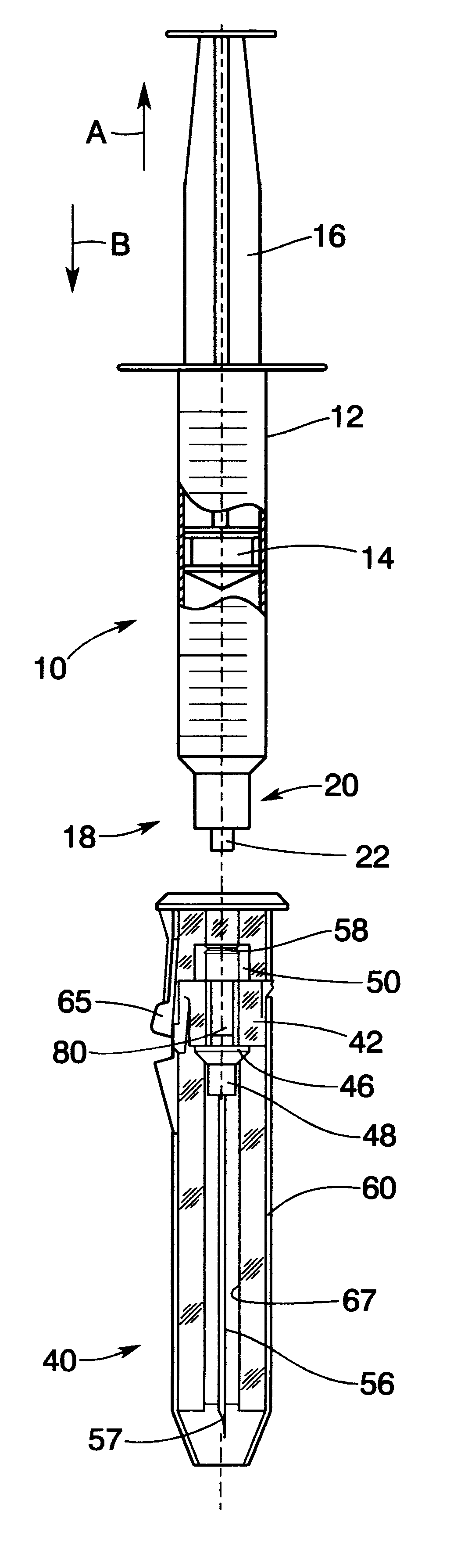
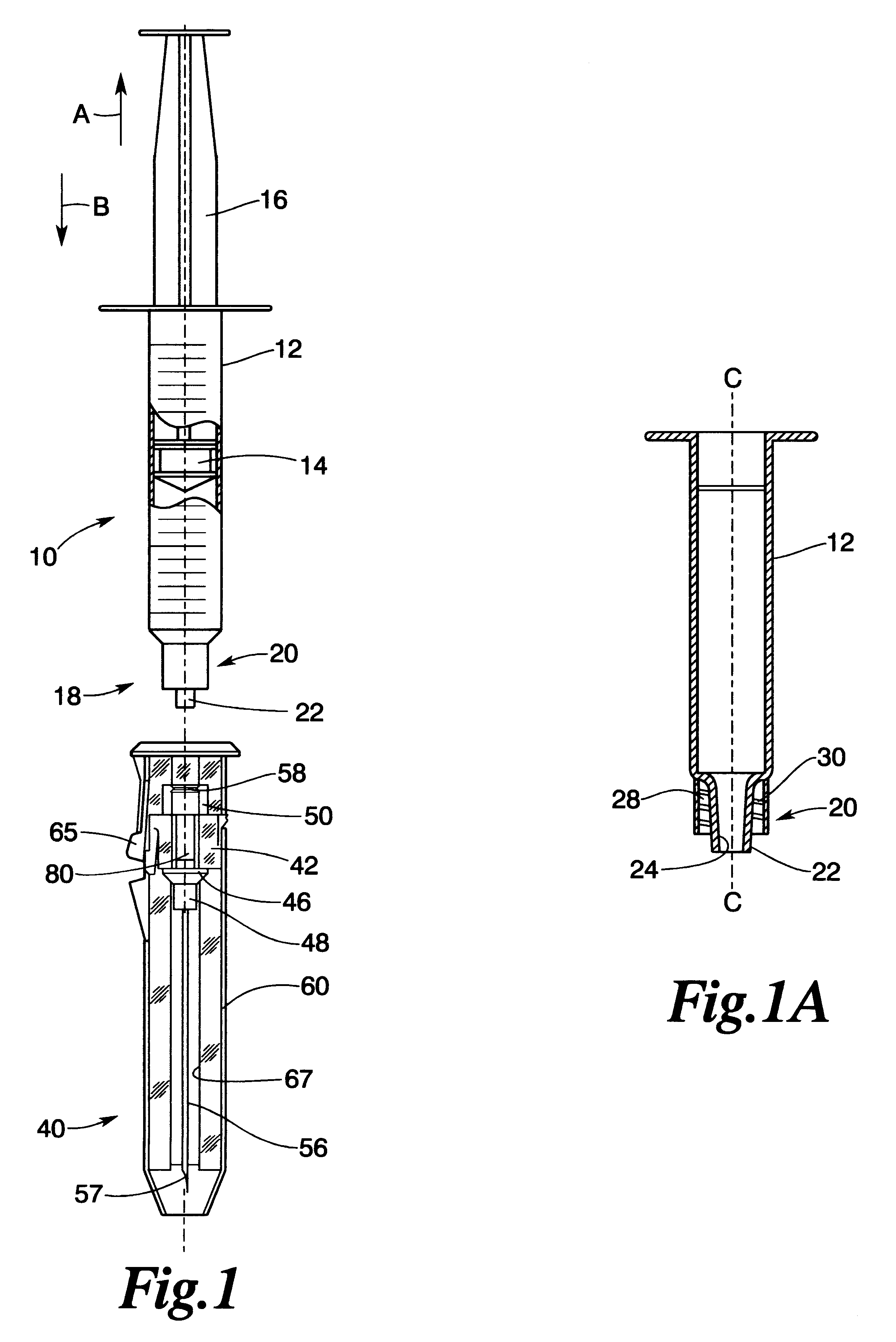
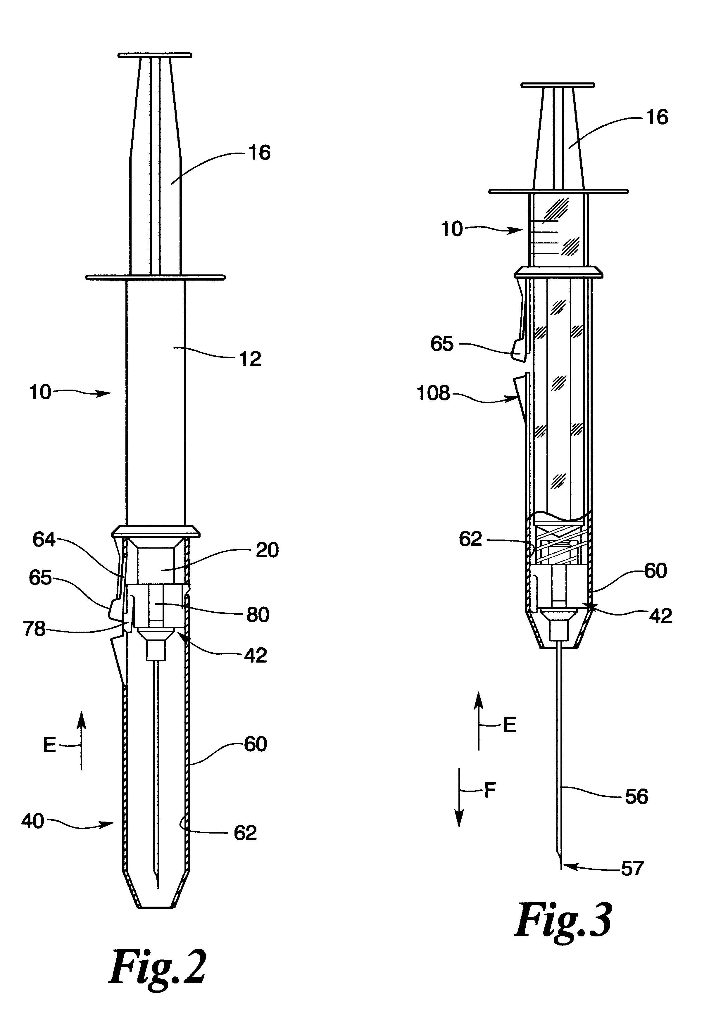
Referring now to the drawings for the purposes of illustrating the present embodiments of the invention only and not for the purposes of limiting the same, the Figures show a selectively lockable needle guard assembly 40 adapted for use in connection with a syringe 10. Syringe 10 has a hollow syringe body 12 that supports a piston 14 therein. See FIG. 1. The piston 14 is attached to a plunger rod 16 that is used to actuate the piston 14 within the body 12 for drawing medicament into the syringe or discharging it therefrom. The forward end 18 of the syringe body 12 has a conventional "luer-lock" attachment portion 20 formed thereon. Such luer-lock connections are known in the art and generally comprise a tapered nose 22 that has a passageway 24 therethrough that communicates with the interior of the syringe body 12. Thus, by pulling the plunger rod in the "A" direction, a medicament may be drawn into the body 12 of the syringe 10 through the passageway 24 in the nose 22. The medicame...


PUM


Abstract

A needle guard assembly for a syringe adapted to receive a hypodermic needle assembly. The guard assembly includes a needle guard that is slidably mounted on a needle-supporting hub. The needle guard may be moved from a latched position wherein the needle is fully protected by the guard to a position wherein the injection end of the needle is exposed. The assembly further includes a locking mechanism for permanently locking the needle guard in an extended position over the needle to prevent further use of the needle and to facilitate safe disposal of the assembly.

Description

Not applicable.FEDERALLY SPONSORED RESEARCHNot applicable.1. Field of the InventionThe subject invention relates to medical devices and, more particularly, to hypodermic syringes with protective needle guards.2. Description of the Invention BackgroundSyringes equipped with hypodermic needles are commonly used to inject precise amounts of medicament subcutaneously. In the past, hypodermic needles were provided with a removable needle shield that encased the needle prior to use. To use the syringe, the shield was removed from the needle and retained by the user so that it could be replaced after the injection had been completed. Replacement of the shield on the contaminated needle was fraught with risk and required extreme care on the user's part to avoid inadvertent sticks by the contaminated needle. Furthermore, if the user lost or misplaced the shield during the injection process or otherwise failed to replace it after use, the syringe was disposed of with an exposed contaminated n...

Claims


Application Information

Patent Timeline
Patent Type & Authority Patents(United States)
IPC IPC(8): A61M5/32A61M5/24
CPCA61M5/3243A61M5/24A61M2005/3253A61M2005/2414
Inventor GETTIG, WILLIAM A.SHOOK, LARRY E.
Owner GETTIG TECH
Why Eureka
Try Eureka