
Method for fine tuning of a robot program

a robot and program technology, applied in the field of robot program fine tuning, can solve the problems of time-consuming and labor-intensive programming of robots by teaching, limited application accuracy, and difficulty for human eye to find the correct position and orientation of tools, and achieve the effect of increasing the accuracy of applications

Inactive Publication Date: 2004-12-28
ABB (SCHWEIZ) AG
View PDF15 Cites 31 Cited by
  • Summary
  • Abstract
  • Description
  • Claims
  • Application Information

AI Technical Summary

Benefits of technology

The object of the present invention is to provide a method for fine tuning a robot program, which method increases the accuracy of the application.
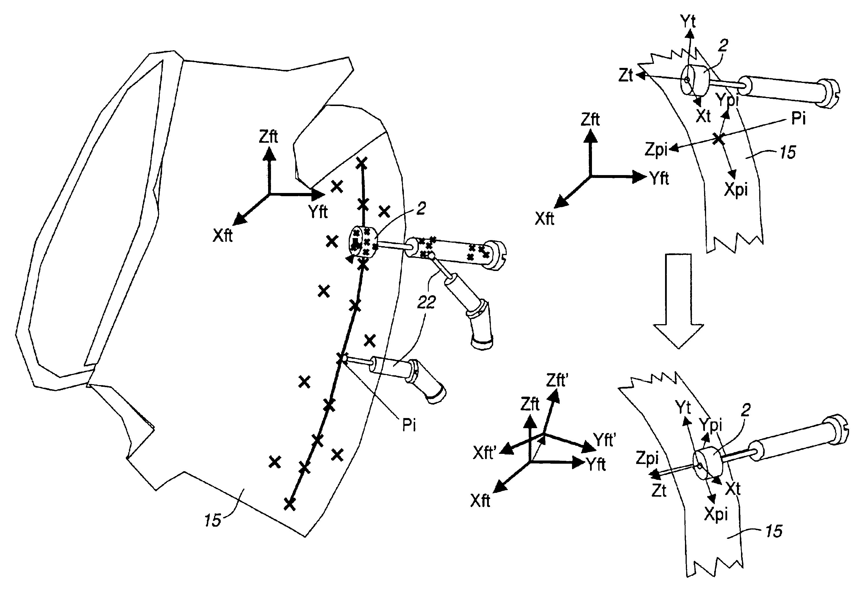
According to an embodiment of the invention, the fine tuning is repeated for a following pose on the path, and comprises: calculating said following programmed pose in the local fine tuning coordinate system of the previous pose, running the robot program to said following programmed pose in the local fine tuning coordinate system of the previous pose, measuring the difference between the obtained following pose and the desired following pose, adjusting a copy of the local fine tuning coordinate system of the previous pose so that the following obtained pose approaches the desired pose, and saving the adjusted copy of the local fine tuning coordinate system as a local fine tuning coordinate system for said following pose. Thus, the local fine tuning coordinate system for the previous pose is used for determining a local fine tuning coordinate system for the following pose on the path. The advantage with this is that the less data is needed to define the fine tuning if poses close to each other share a fine tuning coordinate system with the same adjustment.
According to an embodiment of the invention the obtained pose of the tool and the desired pose of the tool on the work object, are measured by means of a positioning measuring unit and the difference between the obtained and desired pose are calculated as the difference between the measurements from said measuring unit. Advantages with using a positioning measuring unit for the measurements are that the positioning measuring unit is easier and safer to use and provides higher accuracy of the measurements than measuring with the robot.
According to an embodiment of the invention the method comprises: adding an offset distance to the programmed pose, running the robot program to said programmed pose with the offset distance added and removing the offset distance before reprogramming the pose. To make it easier to measure on the work object and the tool, an offset distance is added to the poses on the programmed path. For example, if the tool is used to mill, grind or drill internal structures on the work object, an offset distance has to be added to the path positions to make it possible to perform the measurements. Preferably, said offset distance corresponds to a distance big enough to be able to measure between the tool and the work object with the positioning measuring unit.
Even if the tool is positioned accurately to the desired poses by the fine tuning method according to the previous embodiments, there may still be errors after processing the work object with the robot. That depends on the fact that the robot is not rigid, but compliant to the tool forces. According to an embodiment of the invention, the method further comprises procedures to compensate for the compliance of the robot comprising: measuring at least one pose along said path on a reference work object having a desired geometry, running the robot program for said application, whereby the tool processes a real work object, measuring at least one corresponding pose along said path on the processed real work object, calculating the difference between the measured pose on the reference work object and the corresponding measured pose on the processed work object, adjusting the local fine tuning coordinate system of the pose, in dependence of said calculated difference between the measured poses on the reference work object and on the processed work object, so that the pose on the processed work object approaches the pose on the reference work object, saving the adjusted local fine tuning coordinate system for the pose, and reprogramming the pose, based on the adjusted local fine tuning coordinate system for the pose. As the fine tuning method comprises an additional adjusting of the fine tuning coordinate systems and reprogramming of the poses on the path, the accuracy of the robot application is further improved. Preferably, a plurality of path poses on the reference work object and corresponding path poses on the processed work object are measured, and the fine tuning coordinate systems for the path poses will undergo an additional adjusting according to this embodiment of the invention.

Problems solved by technology

However programming a robot by teaching can be time-consuming, especially if the work object has a complex geometry.
The accuracy of an application is limited mainly by the repeatability of the robot mechanics and the accuracy with which it is possible to move and rotate the tool to the desired position and orientation.
In many high accuracy applications like machining, laser cutting, laser welding etc. the robot repeatability is good enough but it is very difficult for a human eye to find the correct position and orientation of the tool.
Moreover, even if a robot programmer with long programming experience manages to obtain the accuracy needed, it will take a lot of time.
However, when the robot runs the off-line generated program after the calibration, there will still remain errors due to errors in the robot kinematic and error in the calibration of the object and tool coordinate system.
Therefore, the calibration methods used today for calibrating the coordinate systems, does not provide high enough accuracy for applications having very high accuracy requirements.

Method used


Image

  • Method for fine tuning of a robot program
  • Method for fine tuning of a robot program
  • Method for fine tuning of a robot program

Examples


Embodiment Construction

The robot application selected to describe the method according to the invention is machining, but the method can as well be used for any type of application, where high accuracy is needed.

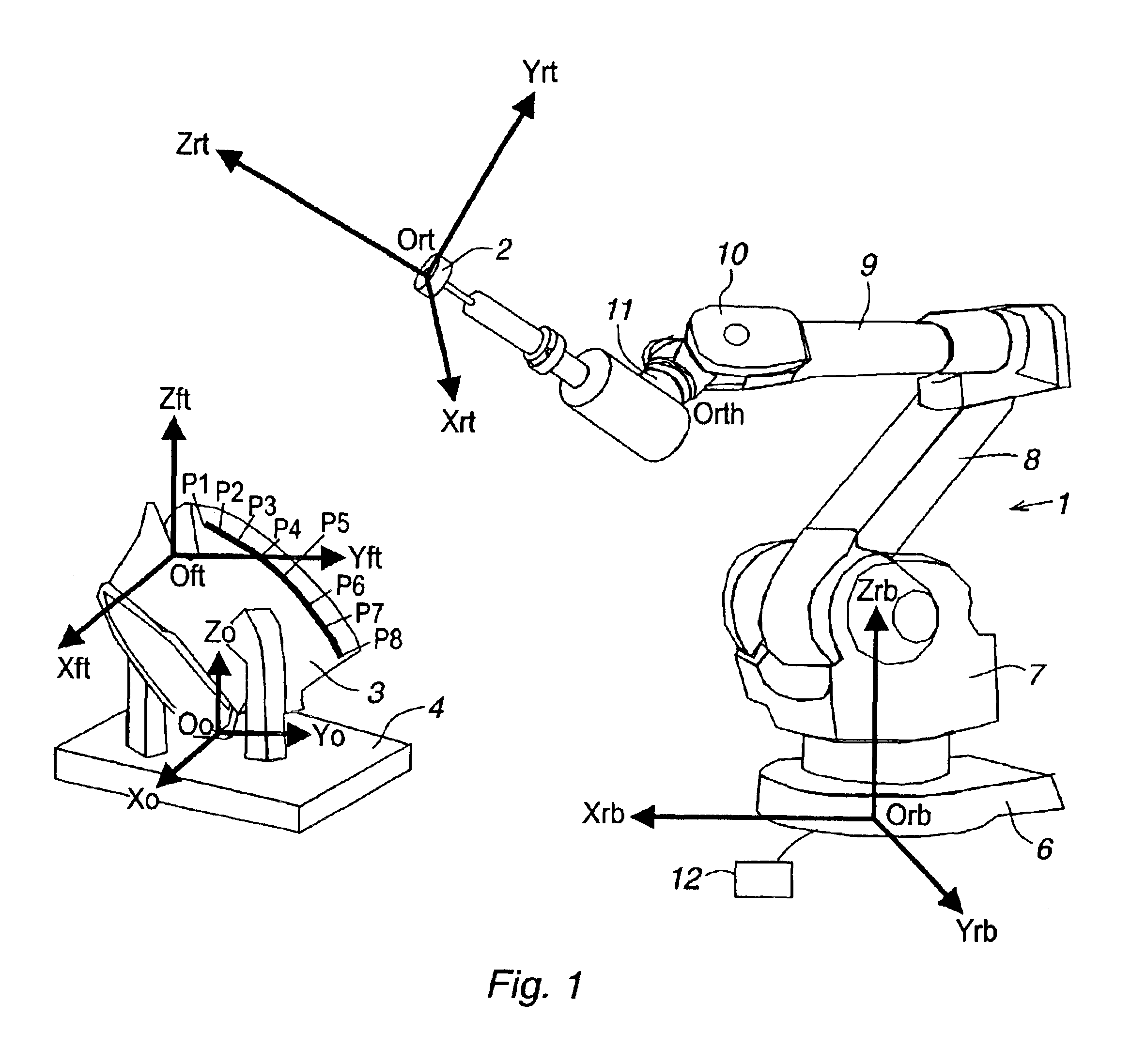
FIG. 1 shows a robot application comprising an industrial robot 1, a tool 2 mounted on the robot, and a work object 3 to be processed by the tool. The work object 3 is attached to a fixture 4. The robot 1 comprises a base 6, which is firmly mounted on a foundation. The robot further comprises a support 7, which is rotateable relative to the base 6 around a first vertical axis. In the upper end of the support 7, a first robot arm 8 is rotatably mounted around a second horizontal axis. In the outer end of the first arm, a second arm 9 is rotatably mounted relative to the first arm around a third axis. The second robot arm 9 is rotatably mounted relative to an inner part of the arm around a fourth axis, coinciding with the length axis of the second arm 9. The second arm 9 supports in its outer end a ...


PUM

PropertyMeasurementUnit
offset distanceaaaaaaaaaa
distanceaaaaaaaaaa
movementsaaaaaaaaaa

Abstract

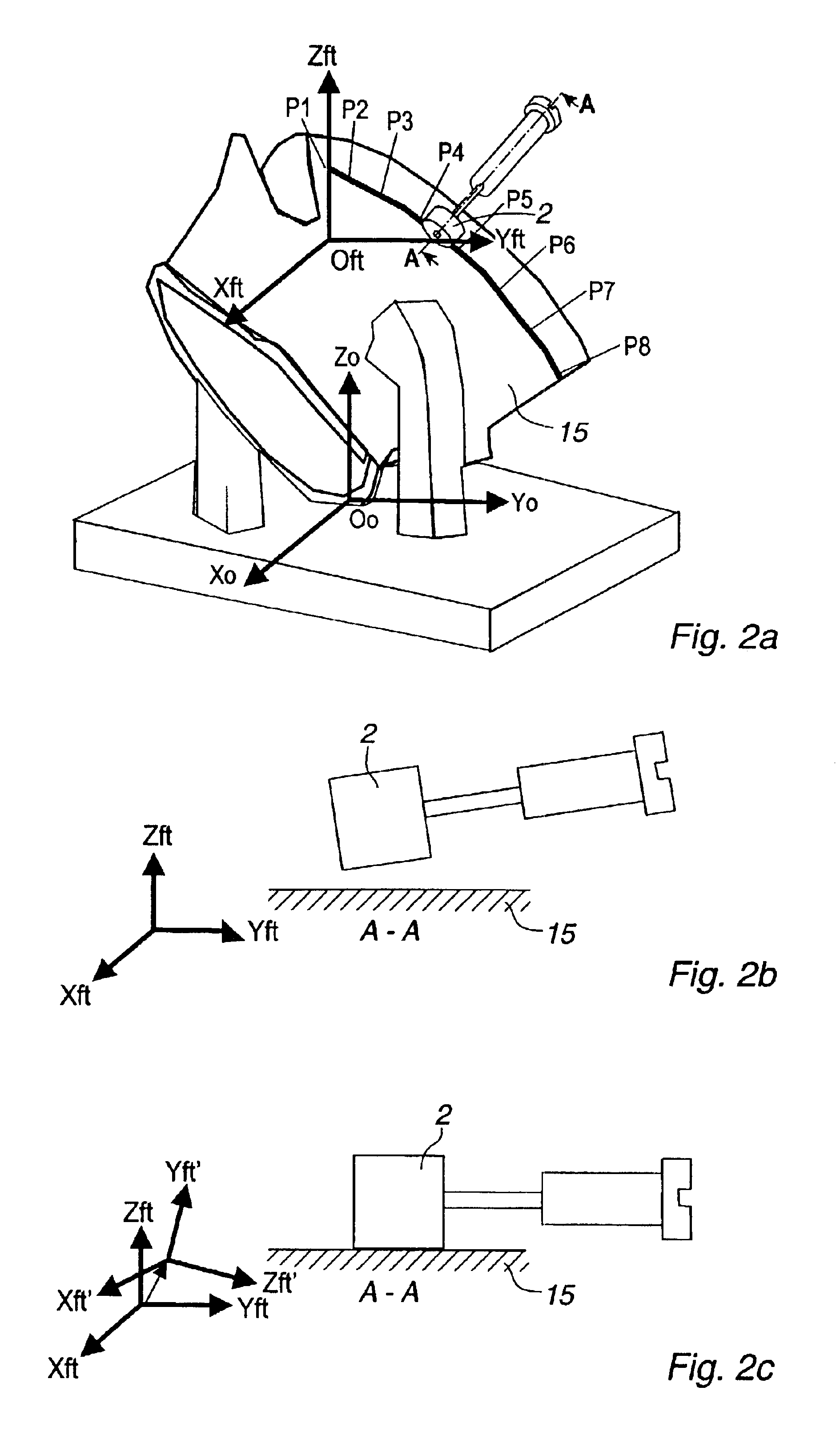
A method for fine tuning of a robot program for a robot application comprising an industrial robot, a tool and a work object to be processed by the tool along a path comprising a number of desired poses on the work object, the robot program comprises a number of program instructions containing programmed poses corresponding to the desired poses, wherein the method comprises: defining a fine tuning coordinate system Xft, Yft, Zft, selecting one of said programmed poses pi, calculating said selected pose in the fine tuning coordinate system, producing program instructions for said selected pose in the fine tuning coordinate system, running said one or more program instructions by the robot, determining the difference between the pose obtained after running the program instructions and the desired pose, adjusting the fine tuning coordinate system in dependence of said difference, producing program instructions for said selected pose in the adjusted fine tuning coordinate system Xft', Yft', Zft'.

Description

The present invention relates to a method for fine tuning of a robot program for a robot application comprising an industrial robot, a tool and a work object to be processed by the tool along a path comprising a number of desired poses on the work object, the robot program comprises a number of program instructions containing programmed poses corresponding to the desired poses. The method according to the invention is useful for fine tuning robot programs being programmed off-line as well as online.The invention is particularly useful in robot application that demands high accuracy, such as different types of machining applications, for example fettling, debarring, milling, sawing, grinding and drilling. The application is also useful in applications such as arc welding, water jet cutting, laser cutting, gluing and assembly.PRIOR ARTA robot program comprises a number of program instructions controlling the movements of the robot. The robot program is based on a number of programmed ...

Claims


Application Information

Patent Timeline
Patent Type & Authority Patents(United States)
IPC IPC(8): B25J9/16G05B19/425
CPCB23K26/04B23K26/0884B25J9/1664G05B19/4083G05B19/425B25J9/1692G05B2219/36407G05B2219/36404
Inventor BROG.ANG.RDH, TORGNYBRANTMARK, H.ANG.KANGAN, ZHONGXUEROSSANO, GREGORYLI, XIONGZISUN, YUNQUANTANG, QUING
Owner ABB (SCHWEIZ) AG
Learn More