Method and apparatus for directional boring

a directional boring and method technology, applied in the direction of directional drilling, drilling machines and methods, drilling accessories, etc., can solve the problems of large displacement work, high weight, and difficulty in directional drilling, and achieve low mechanical outlay, high directional stability, and low wear

Inactive Publication Date: 2001-03-13
TRACTO TECHN PAUL SCHMIDT SPEZIALMASCHEN
View PDF15 Cites 19 Cited by
  • Summary
  • Abstract
  • Description
  • Claims
  • Application Information

AI Technical Summary

Benefits of technology

This invention provides a way to bore holes that require minimal equipment and have good control over their movement through curved paths. It reduces wear on machinery while still being highly effective at directing drilling tools towards specific targets.

Problems solved by technology

The technical problem addressed in this patent relates to improving the efficiency and accuracy of directional boring operations through the use of improved tools and techniques. Specifically, there is a challenge in achieving effective boring without requiring excessive force or introducing unwanted fluids into the environment. Additionally, existing solutions have limitations in terms of their ability to control soil excavation and prevent unintended deviations from the desired trajectory.

Method used


Image

  • Method and apparatus for directional boring
  • Method and apparatus for directional boring
  • Method and apparatus for directional boring

Examples


Embodiment Construction

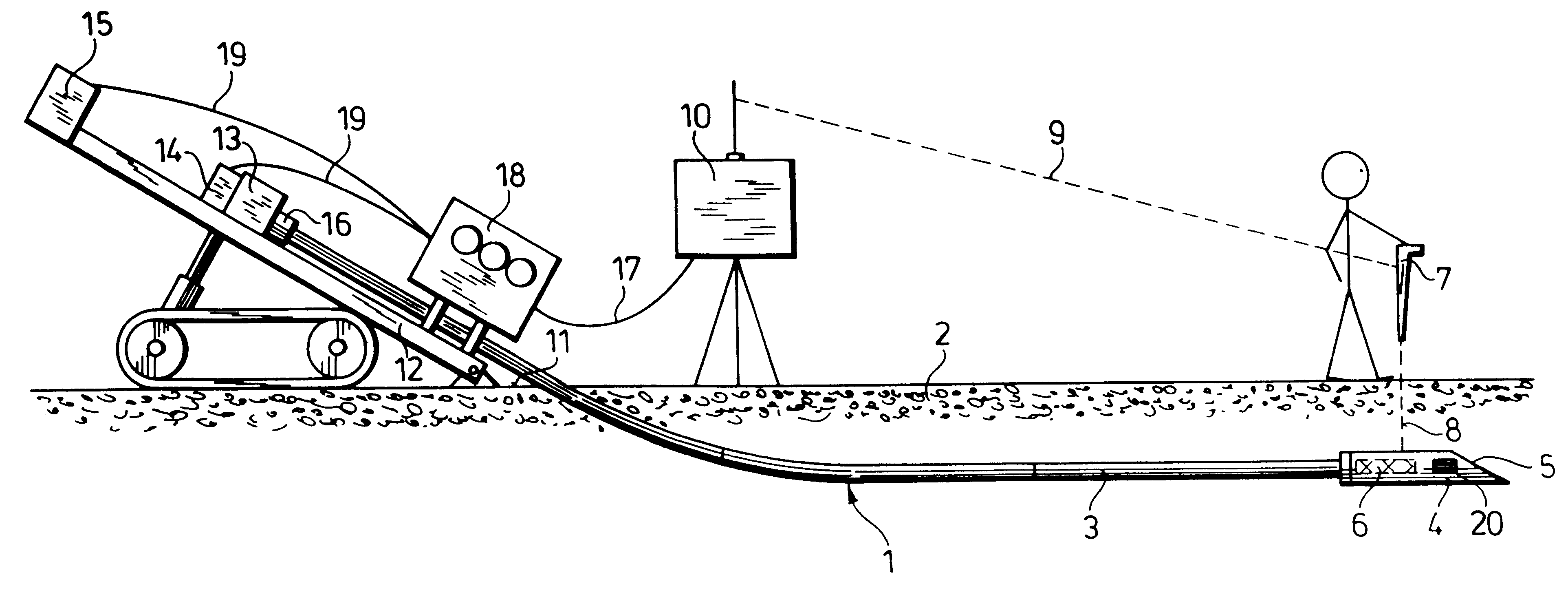
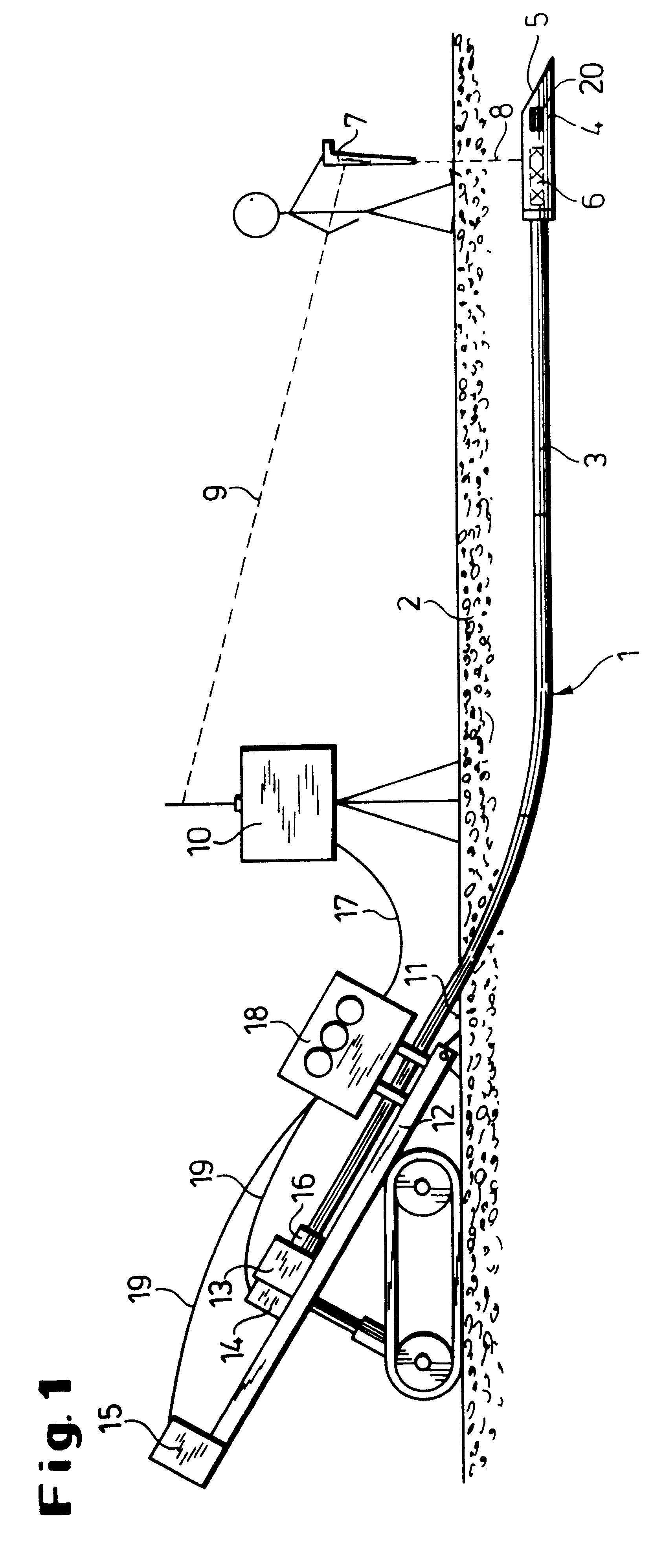
In the method of the invention a bore 1 in the ground 2 is produced by means of an elastic drill string 3 made up of individual pipes. At the end of the drill string 3 there is a drill head 4 with a steering face or bevel 5, which is connected non-rotatably to the drill string 3. The front transverse edge of the bevel acts as an excavating tool and on rotation of the string describes an envelope about the longitudinal axis of the string. In the drill head 4 a transmitter 6 is fitted which transmits data by radio to a receiver 7 which relate to the depth of the drill head 4 below the surface of the ground, the position of the drill head 4 in the ground, its inclination, the angular position of the steering face 5 relative to the longitudinal axis of the drill head 4 and optionally the temperature at the drill head 4. A radio connection between the transmitter 6 and a receiver 7 is indicated by the broken line 8.

A further radio connection 9 communicates the above-mentioned data from t...


PUM


Abstract

In directional boring using a boring apparatus having a driven string and a drill head with an excavating tool moving in an orbit about the longitudinal axis of the string, the tool moves with substantially constant angular velocity when boring straight ahead, but when boring along a curve it is stopped and set in vibration in order to obtain more accurate control of the curve.

Description


Claims


Application Information

Patent Timeline
Owner TRACTO TECHN PAUL SCHMIDT SPEZIALMASCHEN
Why Eureka
Try Eureka