
Boring head method and boring head for a ground boring device

a ground boring and borehole technology, applied in the direction of borehole drives, earth drilling tools, cutting machines, etc., can solve the problems of low directional stability and high resistance to motion in the advancing direction, and achieve the effects of improving the stability of the borehole, reducing the friction of the pulled-up housing, and increasing the cohesion of the displaced earth

Active Publication Date: 2011-05-10
TRACTO TECHN
View PDF24 Cites 8 Cited by
  • Summary
  • Abstract
  • Description
  • Claims
  • Application Information

AI Technical Summary

Benefits of technology

[0012]Based on this prior art, the object of the invention is to provide a boring head which is advantageous in particular for use in displaceable soils and which in particular combines advantages of the conical boring head—for example low resistance to motion—with advantages of the stepped head—for example high directional stability.

Problems solved by technology

These boring heads have the disadvantage of low directional stability, so that the device is deflected from the desired path by lateral forces which are produced by striking an obstacle or by inhomogeneity within the earth.
A disadvantage is that high resistance to motion occurs in the advancing direction due to the stepped surfaces situated perpendicularly to the longitudinal axis.

Method used


Image

  • Boring head method and boring head for a ground boring device
  • Boring head method and boring head for a ground boring device
  • Boring head method and boring head for a ground boring device

Examples


Embodiment Construction

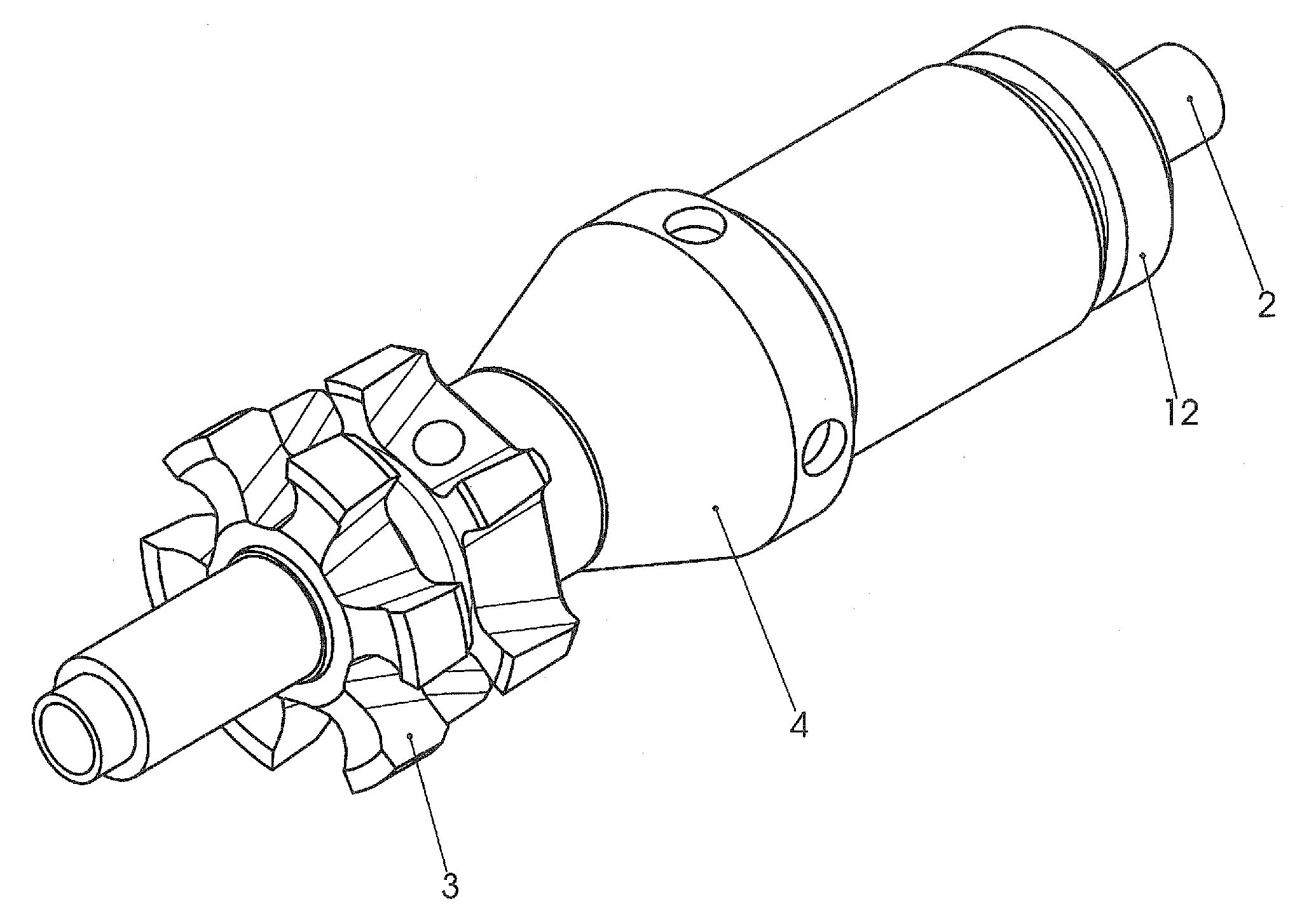
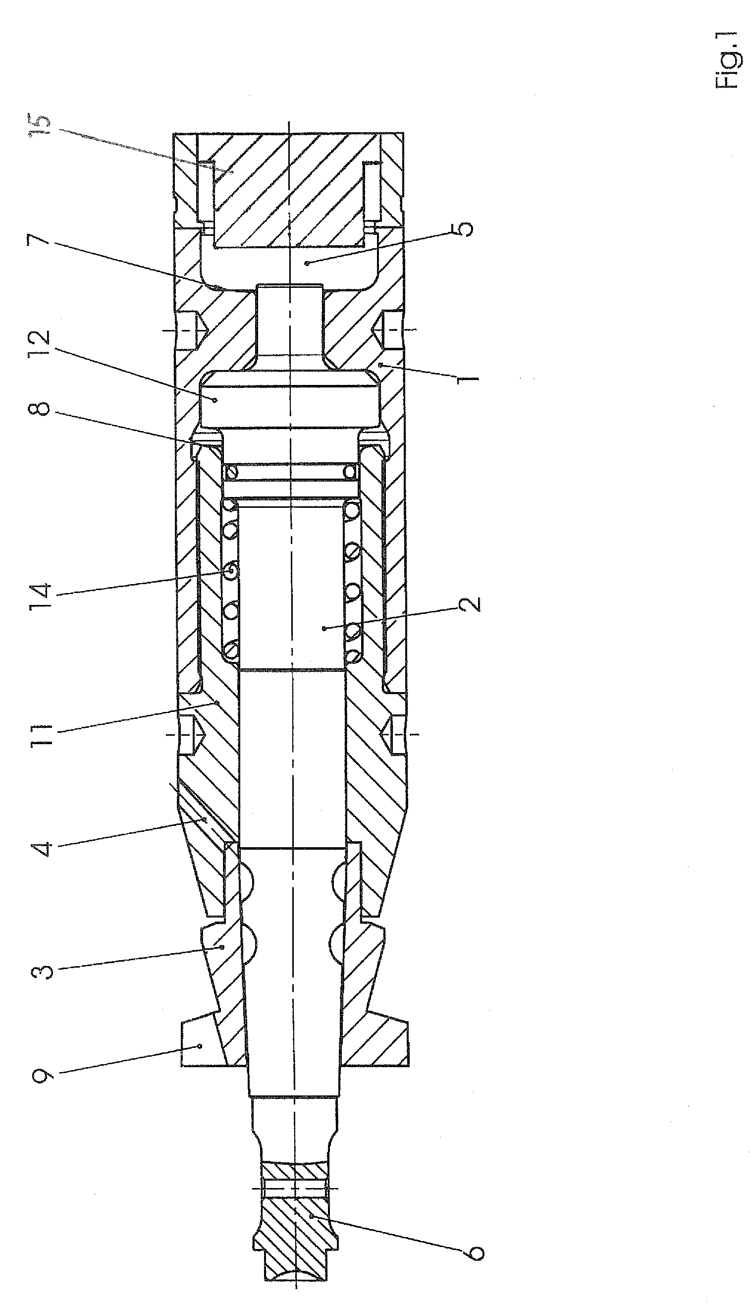
[0063]FIG. 1 shows the front part of a ram boring device, consisting of a housing 1 and a boring head according to the invention connected thereto, in a first embodiment.

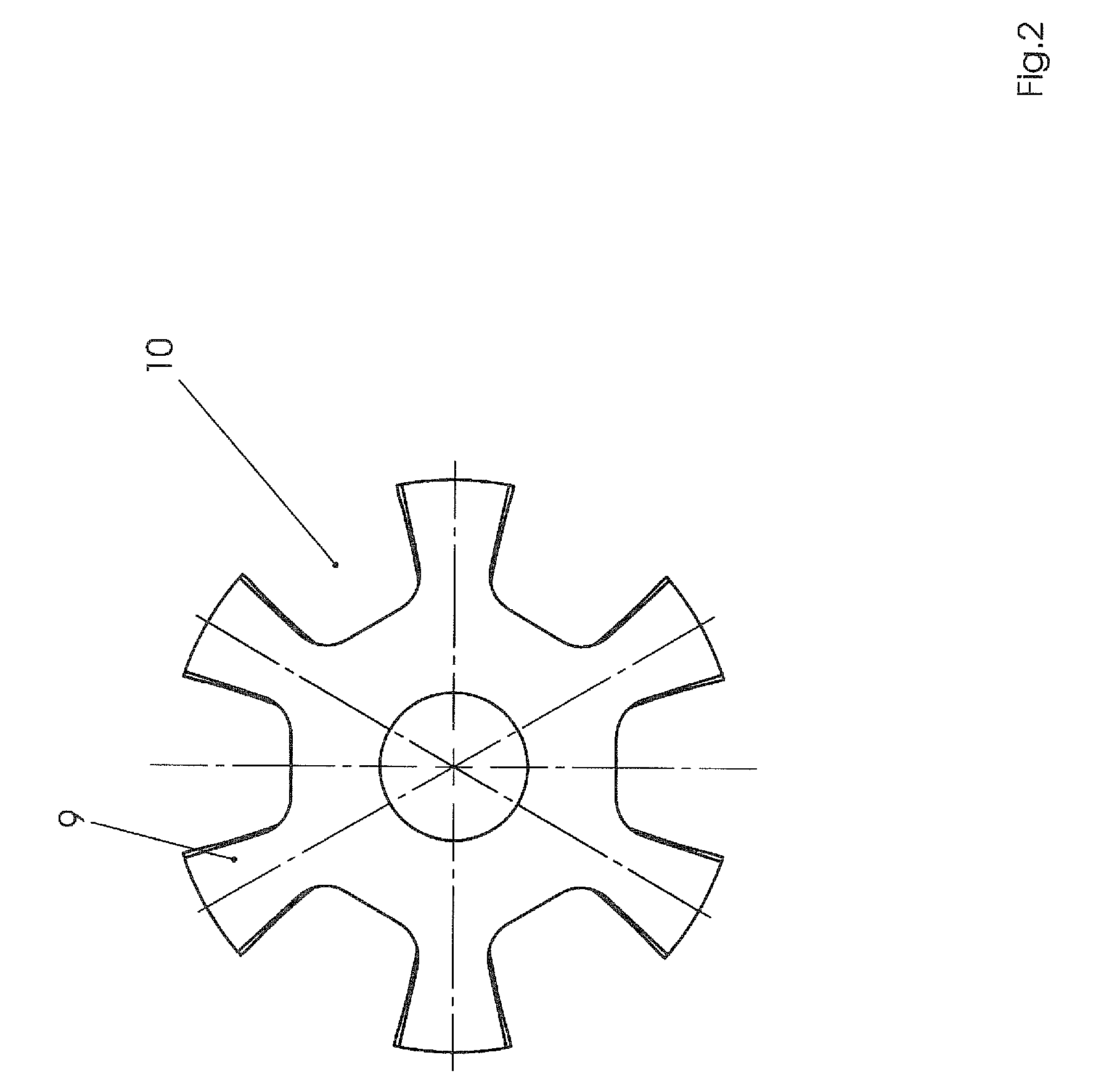
[0064]The boring head essentially comprises the following components: percussion bolt 2, cutting ring 3 and displacer 4. In this embodiment, the percussion bolt 2 and cutting ring 3 together form a first boring head section which is axially movable relative to the second head section, here in the form of the displacer 4, and the third head section 11. To this end, the displacer 4 and the third head section 11 are guided on the percussion bolt 2.

[0065]The rear end of the percussion bolt 2 projects into a working space 5 of the housing 1 in which a percussion piston 15, driven by a pressure fluid, moves in a reciprocating manner. For the forward movement of the ram boring device, the percussion piston 15 first of all strikes that end of the percussion bolt 2 which projects into the working space 5 and accelerates said...


PUM


Abstract

The invention relates to a boring head for a ground-boring device displacing earth with a percussive action, comprising at least three boring head sections, of which the first section has a form optimized for the loosening and for guiding the device, the second section is optimized with regard to the radial displacement of the earth with low resistance to motion, and the third section has a fixed connection to the housing of the ground-boring device. Improved transmission of the advancing forces to the earth and consequently an improved advance of the ground-boring device can be achieved by at least two of the boring head sections being designed so as to be axially movable relative to one another in the longitudinal direction.

Description

CROSS-REFERENCES TO RELATED APPLICATIONS[0001]This application is the U.S. National Stage of International Application No. PCT / EP2005 / 007286, filed Jul. 6, 2005, which designated the United States and has been published as International Publication No. WO 2006 / 002997 and which claims the priority of German Patent Applications, Serial No. 10 2004 032 551.0, filed Jul. 6, 2004, and Serial No. 10 2005 031 707.3, filed Jul. 5, 2005, pursuant to 35 U.S.C. 119(a)-(d).BACKGROUND OF THE INVENTION[0002]The invention relates to a boring head for a ground-boring device.[0003]To produce boreholes in the field of horizontal boring, it is known to use “moles”, which have a reciprocating percussion piston controlled via a drive fluid. This piston transmits its kinetic energy when striking a contact surface of the housing or of the boring head and drives the ground-boring device step by step through the earth.[0004]In this case, the boring head of the device fulfills two functions. Firstly, said bo...

Claims


Application Information

Patent Timeline
IPC IPC(8): E21B10/40
CPCE21B7/26E21B4/145E21B7/046
Inventor PUTTMANN, FRANZ-JOSEF
Owner TRACTO TECHN
Learn More