Snow sled with dual-mode braking system

a braking system and snow sled technology, applied in the field of snow sleds, can solve the problems of difficult or impossible to apply braking force to one pedal, difficulty in controlling the sled, and difficulty in small increments of braking force, so as to promote directional stability

Inactive Publication Date: 2007-06-19
STEVENS BOB F
View PDF17 Cites 9 Cited by
  • Summary
  • Abstract
  • Description
  • Claims
  • Application Information

AI Technical Summary

Benefits of technology

[0011]In general terms, the present invention is a snow sled with a braking system with brake elements that can be actuated operated by foot pressure or by an auxiliary brake actuation system that uses hand-operated cable actuators, or by a combination of the two brake actuation systems. The brake pedals are positioned laterally equidistant from the frame's longitudinal centerline, such that when braking force is applied equally to both pedals, the resultant braking force will be substantially in alignment with the frame centerline, thus promoting directional stability during hard braking.
[0012]The brake pedals may be interconnected by a bridging structure such that both pedals will tend to move toward the engaged position even when foot pressure is applied to only one pedal. In this embodiment, the auxiliary brake actuation system comprises a sheathed cable connected at one end to the underside of the bridging structure at a point below the pivot axis of the pedal assembly, and at the other end connects to a bicycle-style actuator lever mounted to the sled's handlebars or steering wheel. Squeezing the actuator lever exerts a tensile force on the cable which is in turn applied to the brake pedal assembly at a point below the brake pedal pivot axis, thus rotating the brake shoes toward the front of the sled. This causes the brake pads to move forward and downward, and ultimately below the plane of the skis. Accordingly, when the sled is being used on a snow surface, the brake pads may be deployed in the engaged position (i.e., brakingly engaging the snow surface) either by applying foot pressure to the foot rest sections of the brake pedals, or by squeezing the actuator lever, or by doing both.
[0013]In an alternative embodiment, the brake pedals are independently mounted to the sled frame and have independent cable-type auxiliary actuation systems. This arrangement allows even greater differential braking ability, while maintaining full, non-eccentric foot-braking capability in the event of failure of one or both auxiliary cable braking systems.

Problems solved by technology

In the event that one of the cables breaks or otherwise becomes inoperative, the sled will have braking on one side only, which can be more dangerous than having no braking at all; e.g., applying braking to one side only to a fast-moving sled may cause the sled to skid out of control due to the lateral offset of the braking force.
However, with the foot-operated brakes of the GT Sno Racer™, it is difficult to apply small increments of braking force that may be desirable or advantageous for optimal maneuvering of the sled in certain situations, such as when the rider wishes to execute “trick riding” maneuvers.
Moreover, the brake pedals of the GT Sno Racer™ are structurally interconnected such that it is difficult or impossible to apply braking force to one pedal without applying some amount braking force to the other pedal, due to the inherent structural stiffness of the brake pedal assembly.

Method used


Image

  • Snow sled with dual-mode braking system
  • Snow sled with dual-mode braking system
  • Snow sled with dual-mode braking system

Examples


Embodiment Construction

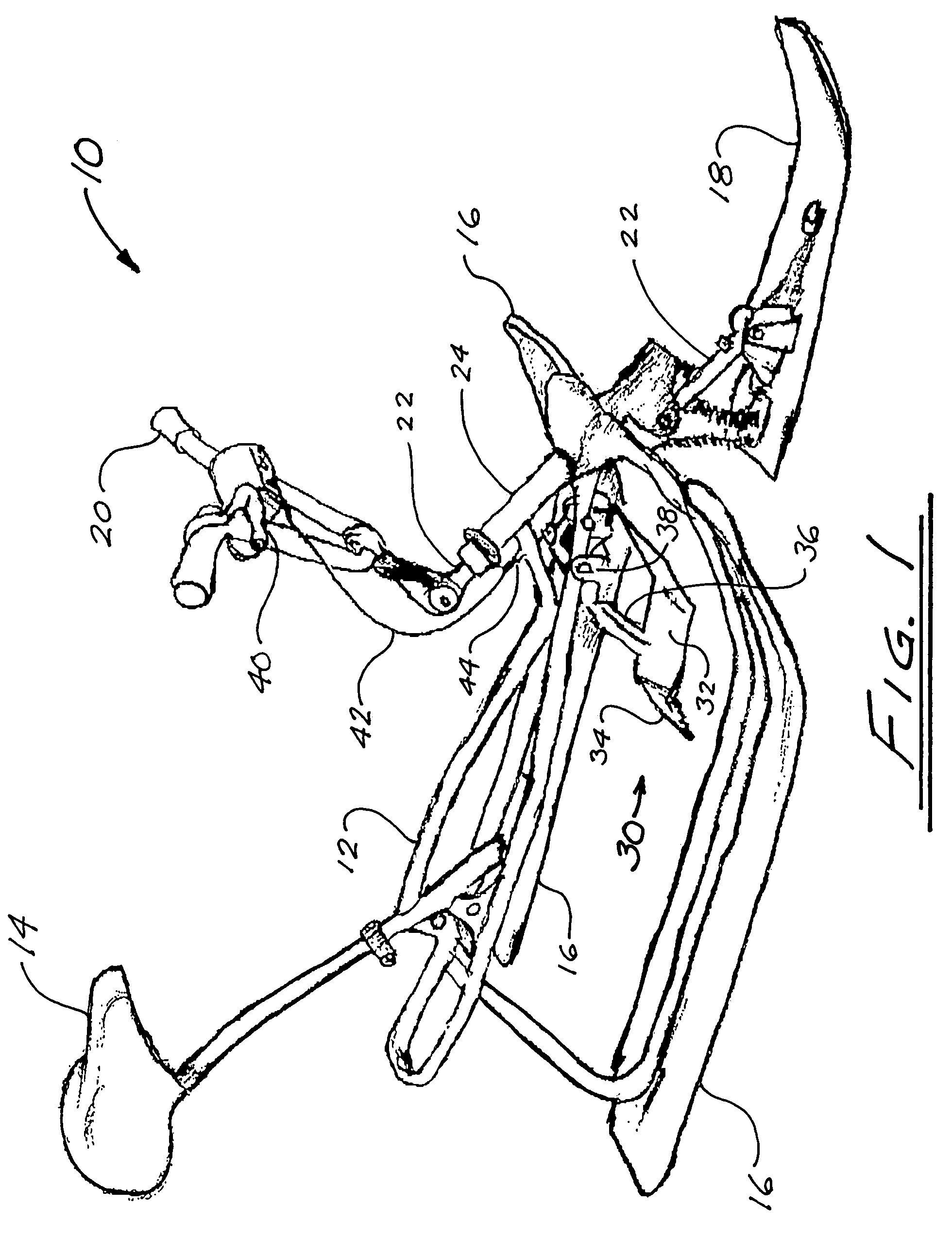
[0040]Referring to FIG. 1, the snow sled accordingly to the preferred embodiment of the invention, generally denoted by reference numeral 10, has a frame 12 with a rider's seat 14. In the Figures, frame 12 is shown constructed of welded tubular members; this form construction is desirable to minimize sled weight, but is not essential to the invention. The frame configuration shown in the Figures is exemplary and non-limiting; other frame geometries and construction arrangements may be used without departing from the scope of the invention. Frame 12 may be fabricated using any suitable materials, which may include steel, aluminum, or titanium.

[0041]In the illustrated preferred embodiment, the sled 10 has a pair of spaced rear skis 16 suitably fastened to frame 12. The sled 10 also includes a set of handlebars 20 connected to a steering shaft 22 swivellingly disposed within a steering sleeve 24 forming part of frame 12, with the steering shaft 22 being connected at its lower end to a ...


PUM


Abstract

Disclosed is a snow sled with brake pedals that can be actuated operated either independently or cooperatively by foot pressure or by manual cable-brake control levers, to press the brake shoes into the snow surface over which the sled is traveling, thereby braking the sled. The brake pedals are pivotably suspended from the sled frame so that the rider's feet can rest upon them. The lower portions of the pedals form brake shoes extending downward and rearward from the foot rest portions of the pedals, such that the brake shoes can be pressed into the snow surface by applying foot pressure to the pedals. Alternatively, the brake pedals can be actuated by a bicycle-style cable-brake lever. Cable-biasing means is provided to keep the brake cable taut when the brake pedals have been partially actuated by foot pressure, so that the cable-brake system remains operatively effective at all times. The brake pedals may be interconnected by a bridging structure such that both pedals will tend to move toward the engaged position even when foot pressure is applied to only one pedal. Alternatively, the brake pedals may be independently operable, with separate cable-brake control systems.

Description

FIELD OF THE INVENTION[0001]The present invention relates in general to snow sleds, and in particular to snow sleds with braking systems.BACKGROUND OF THE INVENTION[0002]There are many known types of recreational vehicles for gliding over snow-covered surfaces. In some types of recreational snow vehicles, such as toboggans, steering is accomplished by selective shifting of the rider's weight, and braking is accomplished by the rider or riders dragging their feet against the snow-covered ground. Other types of snow vehicles include snow sleds having a bicycle-type frame with a pair of fixed rear skis or runners, and a single front ski (or, in some cases, double twin skis) steerably connected to a steering column with handlebars or a steering wheel that is controlled by the rider.[0003]Some snow sleds of this type have no braking mechanisms: see, for example, U.S. Pat. No. 4,168,843 (Hager), U.S. Pat. No. 5,335,925 (Dolson), U.S. Pat. No. 5,580,071 (Yu), and Des. 311,358 (Dallaire). H...

Claims


Application Information

Patent Timeline
Patent Type & Authority Patents(United States)
IPC IPC(8): B62B13/14
CPCB62B17/08B62B13/10B62B5/0433B62B5/0438
Inventor STEVENS, BOB F.
Owner STEVENS BOB F
Why Eureka
Try Eureka