Self-pumping hydropneumatic shock strut with internal level regulation

Inactive Publication Date: 2001-03-20
ZF FRIEDRICHSHAFEN AG
View PDF2 Cites 27 Cited by
  • Summary
  • Abstract
  • Description
  • Claims
  • Application Information

AI Technical Summary

Problems solved by technology

A disadvantage of this invention is that a pressure compensation takes place between the high pressure and the lo

Method used


Image

  • Self-pumping hydropneumatic shock strut with internal level regulation
  • Self-pumping hydropneumatic shock strut with internal level regulation
  • Self-pumping hydropneumatic shock strut with internal level regulation

Examples


Embodiment Construction

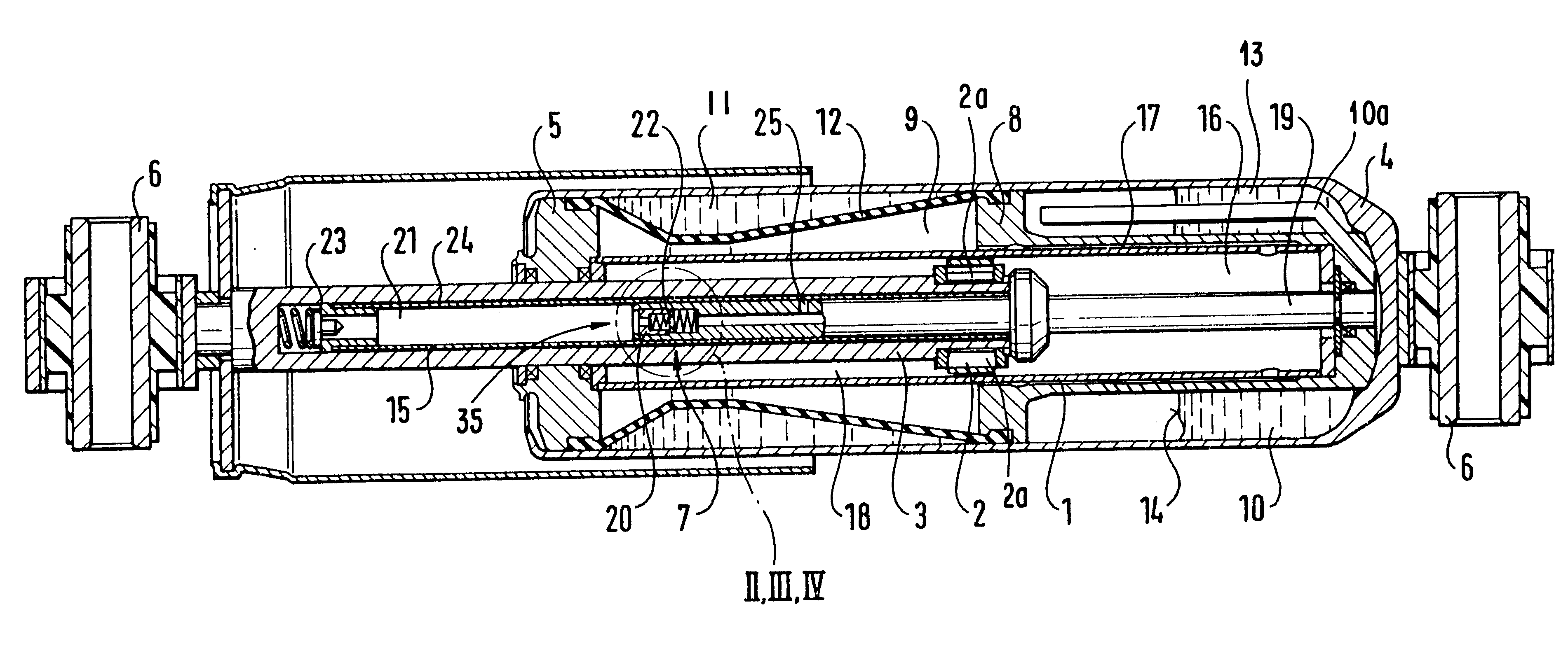
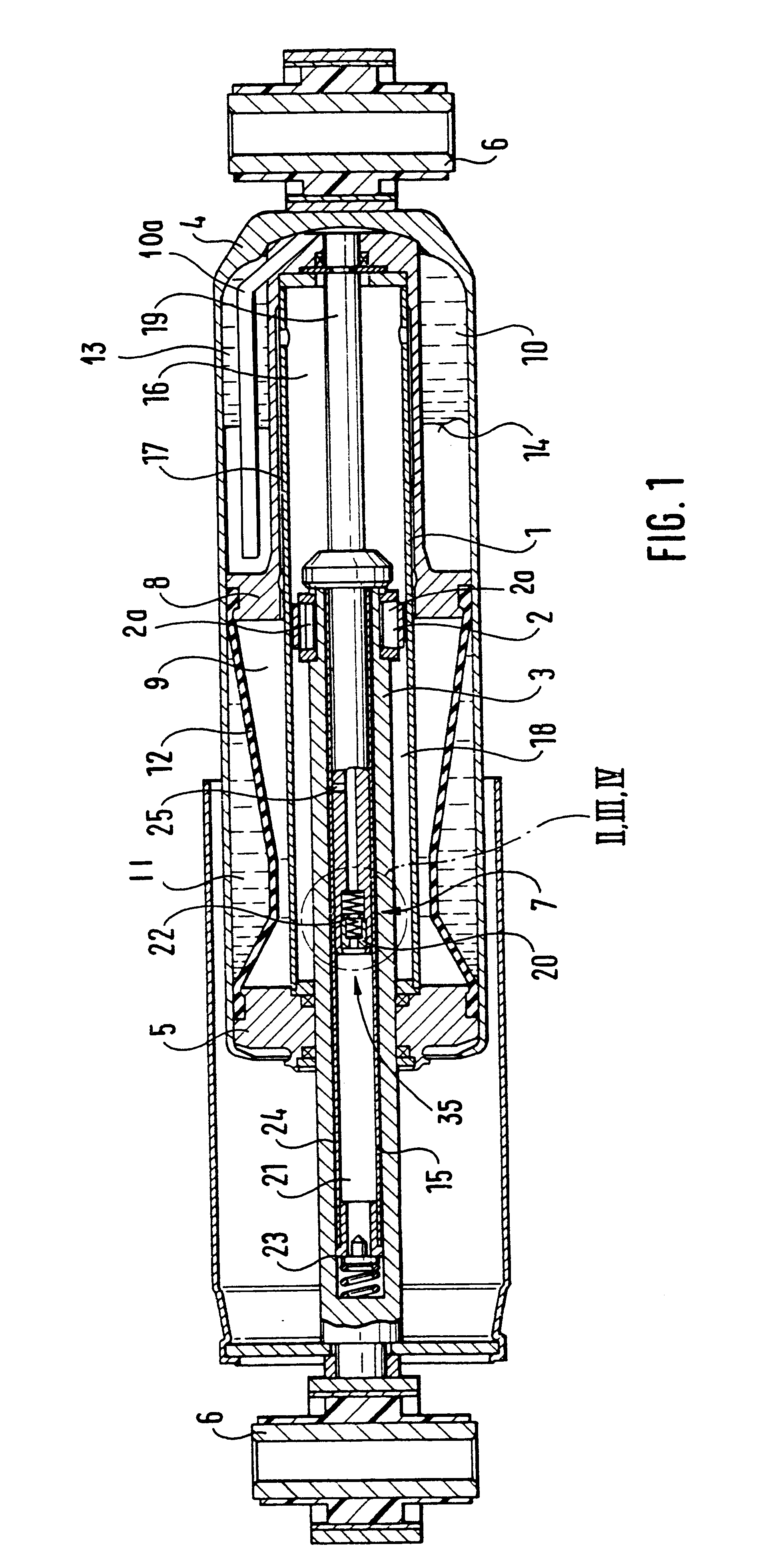
FIG. 1 shows a level regulation device in a shock strut for use in a motor vehicle including a work cylinder 1 in which a piston 2 is slidably mounted at the end of a piston rod 3. The work cylinder 1 is closed on one side by a base 4 and on the other side by a cover 5. The cover 5 has a hole through which the piston rod 3 penetrates and which is sealed around the piston rod 3. The base 4 is fastenable to the body of the vehicle by a fastening element 6 and the piston rod 3 is fastenable to an axle of the vehicle in a manner not shown by a fastening lug at another fastening element 6. The work cylinder 1 is enclosed by an annular compensation chamber that is filled partly with oil and partly with gas and divided by an intermediate wall 8 into a high-pressure chamber 9, 11 and a low-pressure chamber 10. The high-pressure chamber 9, 11 is divided by a diaphragm 12 into an oil space 9 and a gas space 11. In the low pressure chamber 10, oil and a low-pressure gas cushion 13 are not sepa...


PUM


Abstract

Self-pumping hydropneumatic shock strut with internal level regulation for motor vehicles with a work cylinder which is filled with oil and acted upon by pressure by at least one gas cushion arranged in a high-pressure chamber which acts as a spring. The work cylinder is divided into two work spaces by a work piston carried by a hollow piston rod. The work piston has a piston pump which is driven by the spring movements and delivers oil from a low-pressure chamber in the work space connected with the high-pressure chamber. The pump cylinder of the piston pump is formed by the hollow piston rod. A hollow pump rod which is fastened to the work cylinder and carries a suction valve at its front end penetrates into the piston rod and the bore of the hollow pump rod is connected with the low-pressure chamber. A regulating opening of the pump rod is closable as a function of the position of the work piston in the work cylinder and connects the work space connected with the high-pressure chamber with a regulating channel having a choke and opening into the low-pressure chamber. The piston pump is provided with an overload valve in which the suction valve is incorporated.

Description

1. Field of the InventionThe invention relates to a self-pumping hydropneumatic spring strut or shock strut with internal level regulation for use with motor vehicles. The shock strut includes a working cylinder which is filled with oil and acted upon with pressure from at least one gas cushion arranged in a high-pressure chamber and acting as a spring. The work cylinder is divided into two work spaces by a work piston having a hollow piston rod and a piston pump which is driven by the spring movements. One of the work spaces is connected to the high-pressure chamber. The piston pump has a pump cylinder formed by the hollow piston rod and delivers oil from a low-pressure chamber to the work space connected with the high-pressure chamber. A hollow pump rod which is fastened to the work cylinder and has a suction valve at its front end penetrates into the hollow piston rod. The bore of the hollow pump rod is connected with the low-pressure chamber. The hollow pump rod also has a regul...

Claims


Application Information

Patent Timeline
IPC IPC(8): B60G17/044B60G17/04
CPCB60G17/044
Inventor WILMS, BERNDKIRCHNER, HOLGERMEIER, ACHIM
Owner ZF FRIEDRICHSHAFEN AG
Why Eureka
Try Eureka