Venting of molds

Inactive Publication Date: 2001-03-27
MICHELIN & CO CIE GEN DES ESTAB MICHELIN
View PDF16 Cites 19 Cited by
  • Summary
  • Abstract
  • Description
  • Claims
  • Application Information

AI Technical Summary

Benefits of technology

Contrary to the numerous attempts which can be noted, in particular, from the patent references, the present invention does not propose producing a vent of very sophisticated form, nor does it propose producing a vent having movable parts nor using porous materials. Although the clearance between the plug and the hole which receives it is theoretically zero, it

Problems solved by technology

Although the clearance between the plug and the hole which receives it is theoretically zero, it has been found experimentally that the air can leak around the plug at the temperature and pressure levels reached during molding.
There results

Method used


Image

  • Venting of molds
  • Venting of molds
  • Venting of molds

Examples


Embodiment Construction

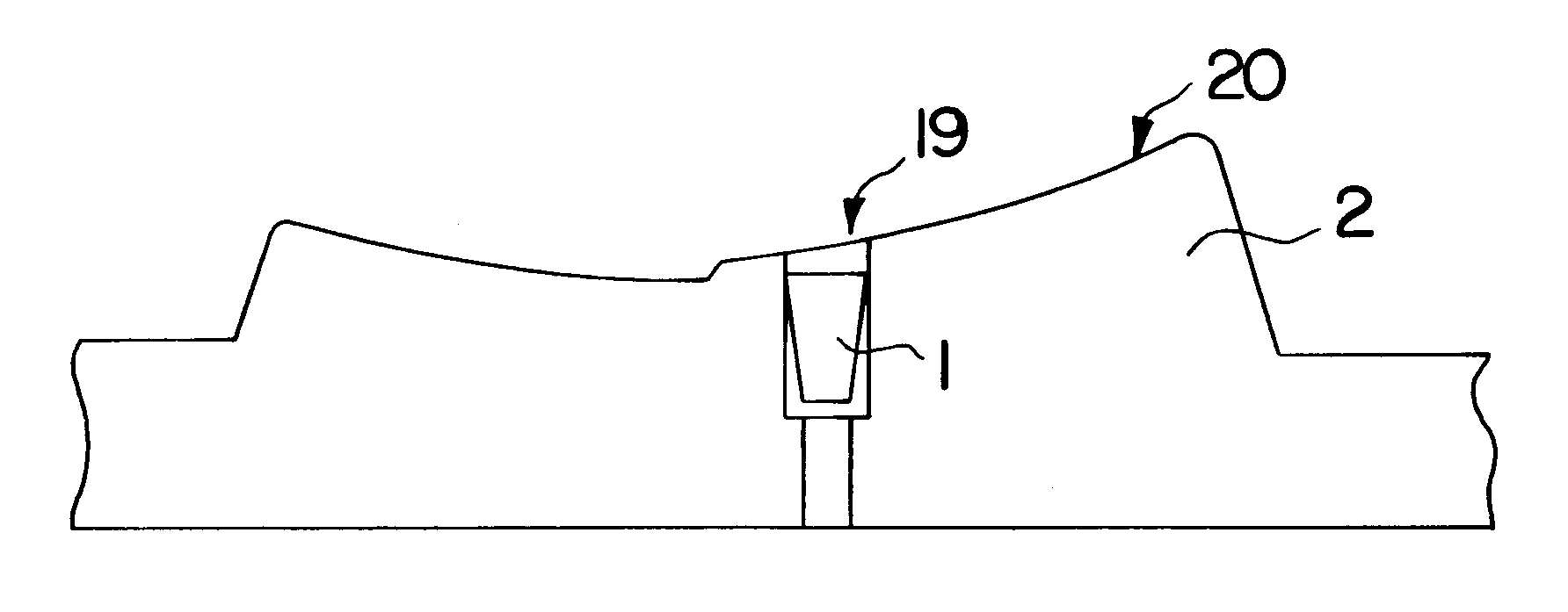
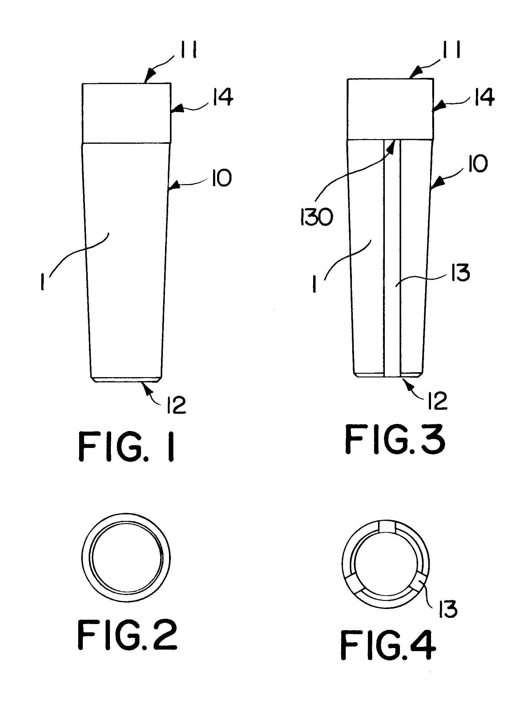
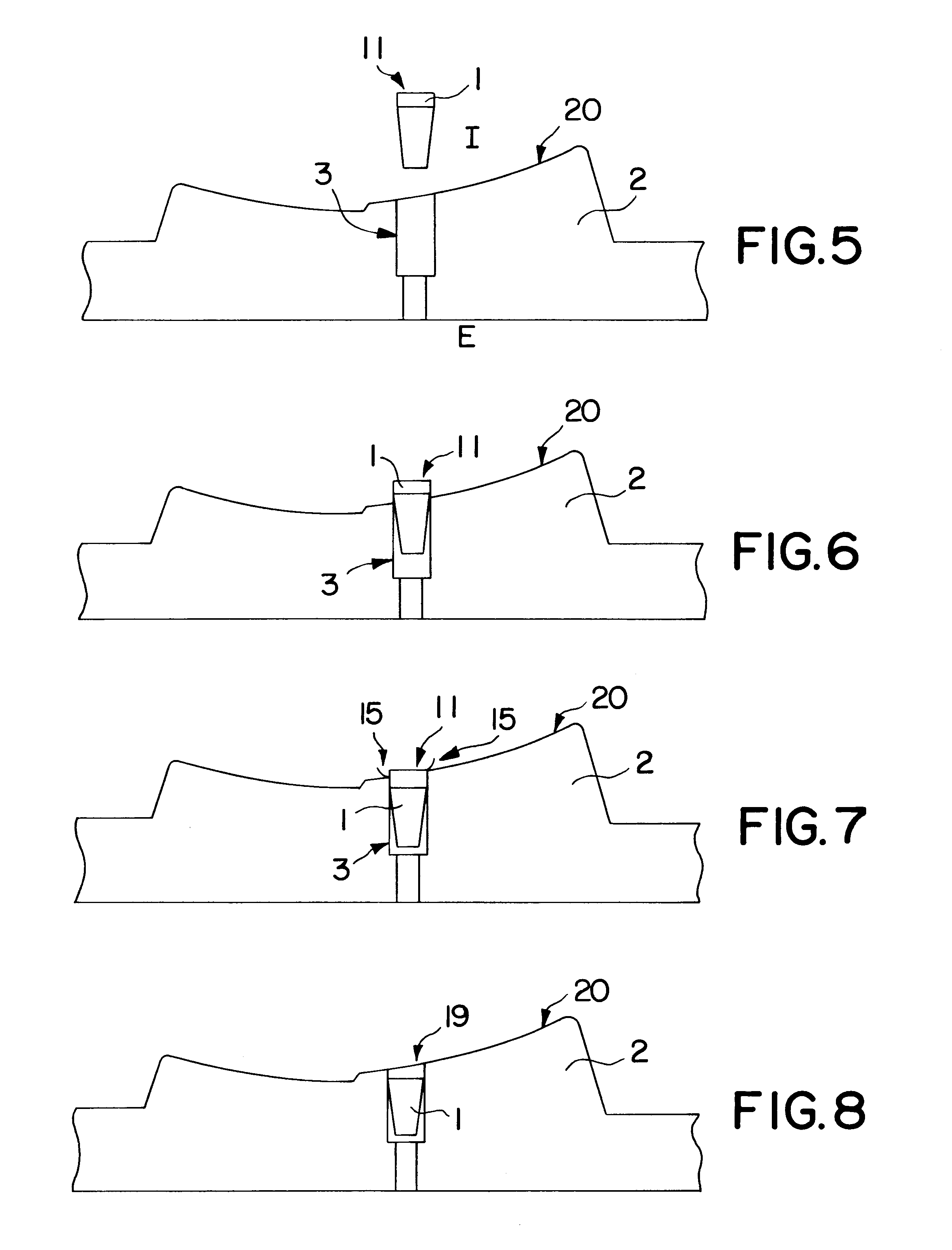
The plug 1 of the invention has the shape of an elongated rod or pin (see FIGS. 1 to 4). The plug has a side surface 10 and at least one end surface 11 and an opposite end 12. The exact shape of this opposite end 12 is not critical; it may be a tapered point or a flat surface, as shown in the drawings. On the side surface 10 it is possible to provide grooves 13 which start at said opposite end 12 and terminate at a distance spaced from said end face 11, as shown in FIG. 3. These grooves are intended to facilitate the passage of air to the outside of the mold.

Such plugs can very easily be provided by molding a plastic material. In accordance with one aspect of the present invention, the grooves 13, when they are present, do not extend to the molding surface of the walls of the tire mold. They therefore do not extend to the end surface 11. A ring 14, having a uniform, non-grooved surface, which is, for instance, cylindrical or slightly frustoconical, remains. As can be clearly noted f...


PUM

PropertyMeasurementUnit
Lengthaaaaaaaaaa
Lengthaaaaaaaaaa
Areaaaaaaaaaaa

Abstract

A mold shell having a hole which extends from the molding surface through said shell up to the outside of said mold. The hole is closed by a plug having a completely air-tight end face which is flush with the molding surface so as to constitute a portion of the molding surface, said plug occupying all of the surface of said hole in the molding surface.

Description

The present invention relates to molds, particularly for the molding of tires, and in particular to venting techniques used in these molds in order to permit the air imprisoned between the mold and a raw tire blank to escape to the outside.Molds for tires are frequently equipped with a number of vents arranged at suitable places. These vents are, for instance, generally holes of small diameter connecting the inner cavity of the mold with the outside of the mold. As it is not possible to produce holes of extremely small diameter due to inherent limitations in the machining techniques, it results that the diameter of these holes is generally sufficient to permit rubber to flow, at least slightly, into said holes when the tire is molded. This is the reason why small burrs of rubber protruding slightly from the outer surface can be noted on the surface of numerous tires.It has been attempted to reduce the dimensions of the vents to a size which is sufficiently small to prevent the raw r...

Claims


Application Information

Patent Timeline
IPC IPC(8): B29C33/10B29K21/00B29L30/00
CPCB29C33/10B29D2030/0617B29L2030/00Y10S425/812B29D30/08
Inventor ESPIE, JACQUESLABARRE, DANIELREY, MAURICE
Owner MICHELIN & CO CIE GEN DES ESTAB MICHELIN
Why Eureka
Try Eureka