Machining device and method for assembling the machining device

a technology of machining device and machining method, which is applied in the direction of metal-working equipment, metal working equipment, manufacturing tools, etc., can solve the problems of increasing the cost of such a machining device, all segments must be manufactured with a high degree of accuracy to one another,

Inactive Publication Date: 2019-12-05
HOMAG GMBH
View PDF0 Cites 0 Cited by
  • Summary
  • Abstract
  • Description
  • Claims
  • Application Information

AI Technical Summary

Problems solved by technology

However, the machining devices described in the prior art have the disadvantage that all segments must be manufactured with a high accurac

Method used


Image

  • Machining device and method for assembling the machining device
  • Machining device and method for assembling the machining device
  • Machining device and method for assembling the machining device

Examples


Embodiment Construction

[0041]Preferred embodiments of the present invention are described below by means of the accompanying figures. Modifications of certain individual features can each be combined with one another individually in order to form new embodiments. The described embodiment example is thereby not to be considered restrictive, but rather this primarily serves the descriptive explanation of the present invention.

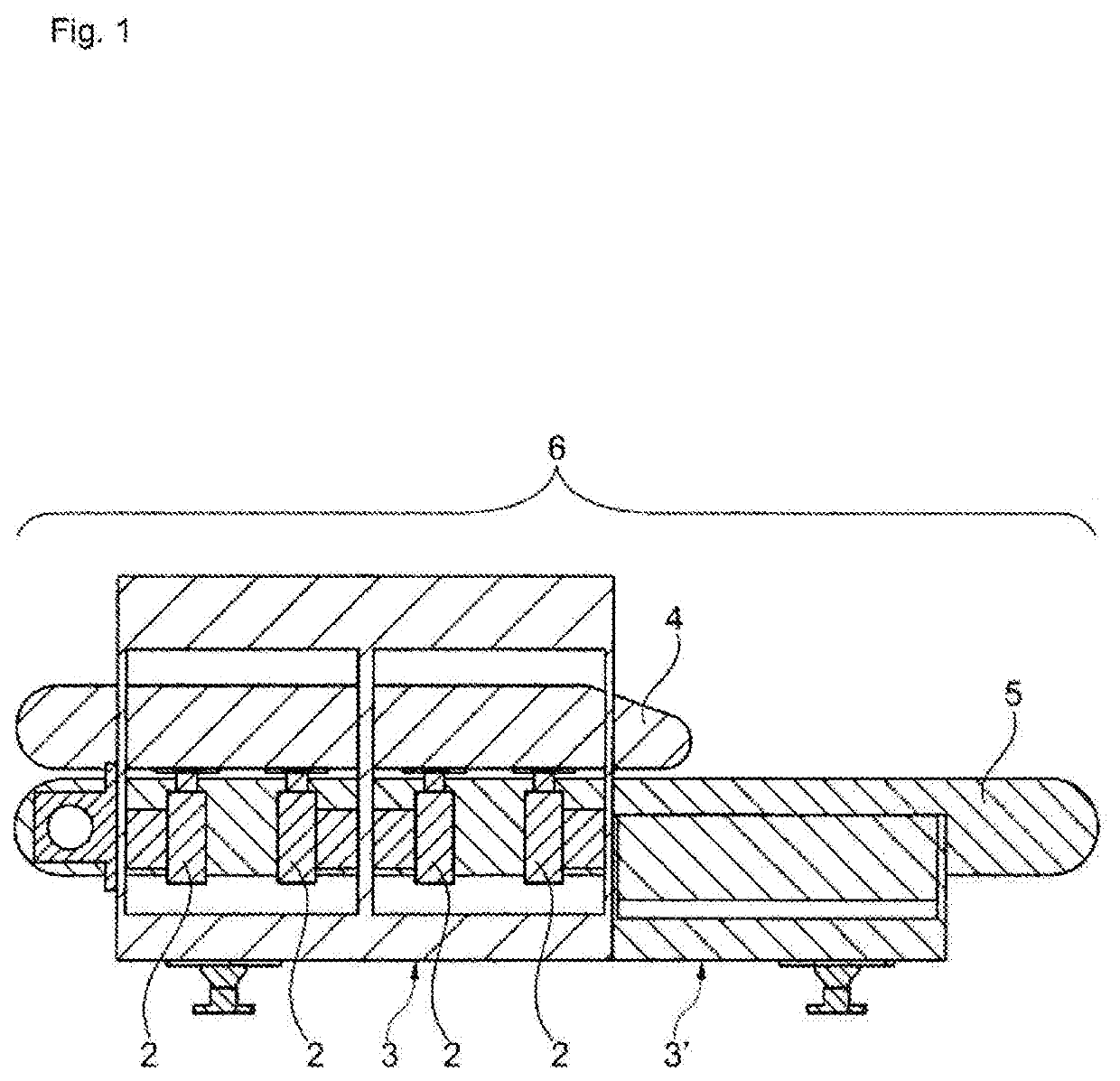
[0042]FIG. 1 shows a machining device 6 in a side view, with the machining device 6 being formed as a throughfeed device. The machining device shown in FIG. 1 was composed of the elements that are described below.

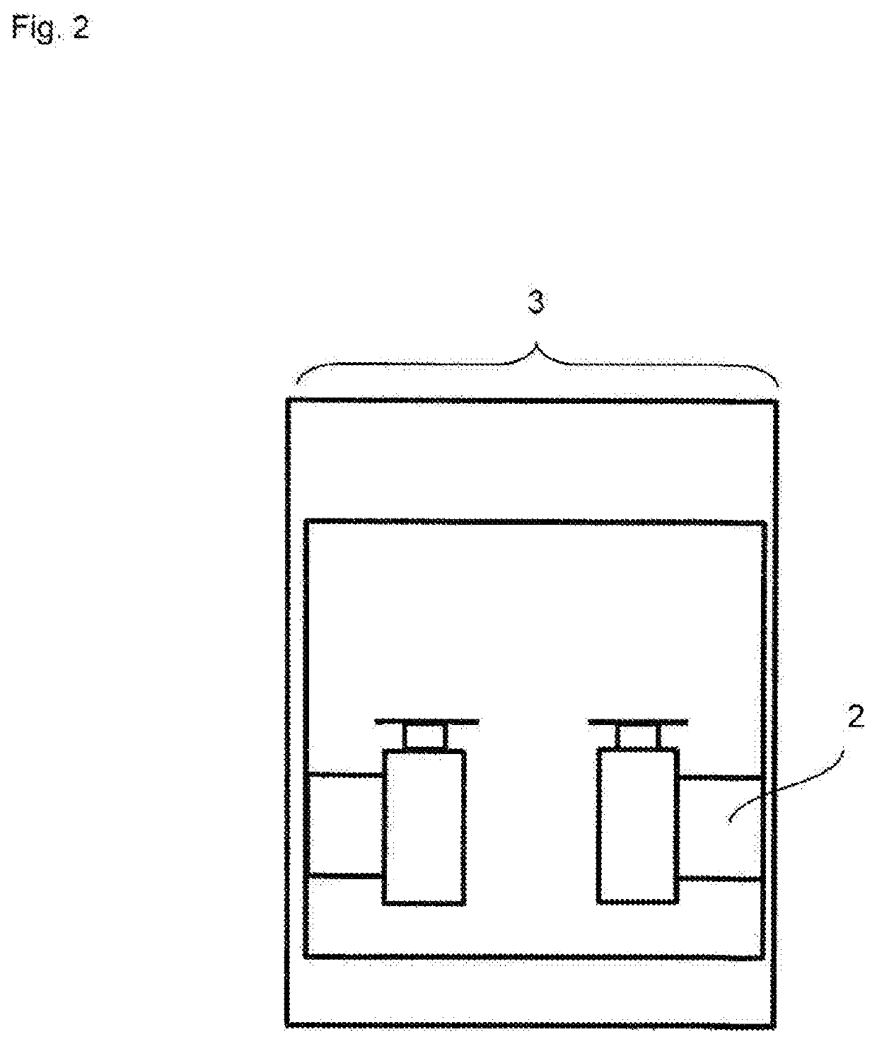
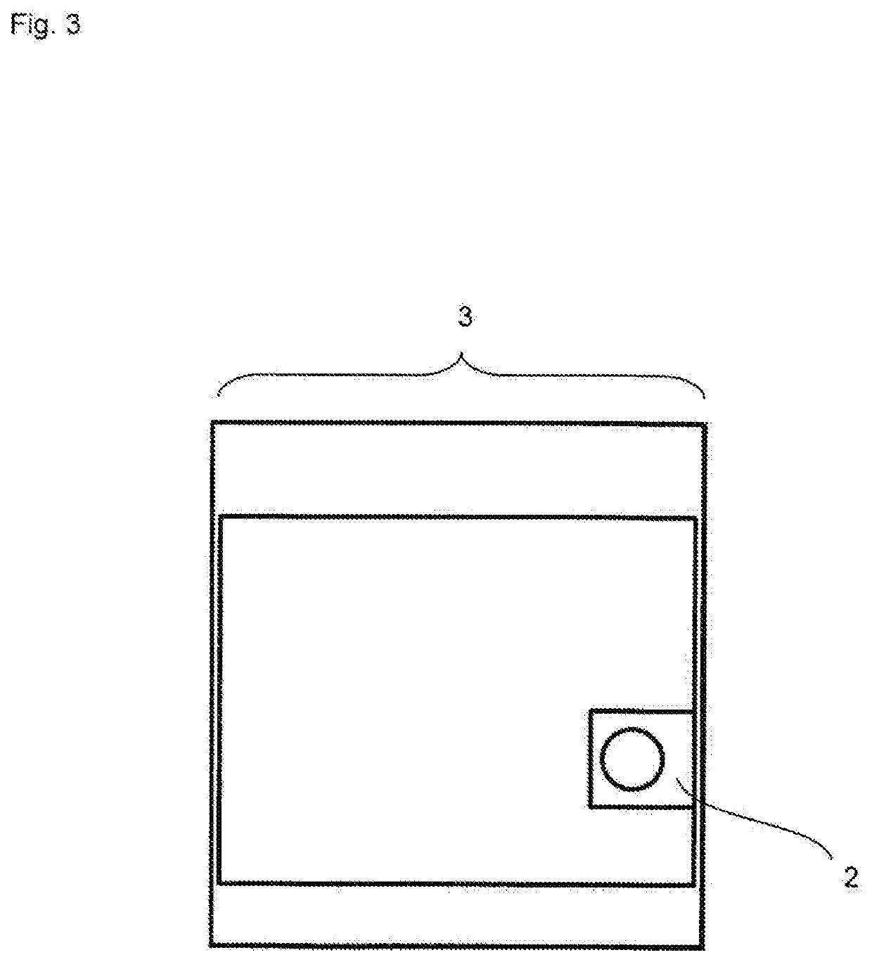
[0043]The machining device 6 comprises a first module 3 and a second module 3′, with the modules 3, 3′ being connected to one another at an interface. In this regard, a continuous chain guide rail 5 of a conveying device is provided. Furthermore, a top pressure device 4 is provided.

[0044]During the assembly of the machining device 6 the modules are aligned, joined together and...


PUM


Abstract

The invention relates to a machining device for machining a workpiece with a continuous guide rail for a conveying device, in particular a chain conveyor, as well as a first module and a second module which are connected to one another by means of the continuous guide rail, in order to form a base body.

Description

[0001]The present invention relates to a machining device which, for example, is used for machining plate-shaped workpieces, as well as a method for assembling a machining device.[0002]In particular, the aforementioned machining device is a throughfeed machine which has one or more conveying devices for moving a workpiece. For example, such a machining device is used in the field of the furniture and component industry in order to machine workpieces of wood, wood materials, composite materials or similar.PRIOR ART[0003]With a throughfeed machine, workpieces moving in a throughfeed direction are machined. For example, within the scope of such a machining, edges can be milled, coating material can be applied / glued to narrow sides, and a post-processing can be carried out. Furthermore, grooves, for example, can be introduced to such a workpiece.[0004]Conventionally, such a throughfeed machine has an inlet area, an aggregate area and an outlet area. In known machines, the machine stand ...

Claims


Application Information

Patent Timeline
IPC IPC(8): B23Q7/03
CPCB23Q7/035B27C9/00B23Q7/03B23Q37/005
Inventor STEEB, MARCELDETTLING, PETERTHUMM, MICHAELBECK, JOCHEN
Owner HOMAG GMBH
Why Eureka
Try Eureka