Clampable pipe coupling

Inactive Publication Date: 2001-03-27
NORMA GERMANY GMBH
View PDF22 Cites 53 Cited by
  • Summary
  • Abstract
  • Description
  • Claims
  • Application Information

AI Technical Summary

Problems solved by technology

But in the case of very high internal pressures, the teeth bend because they are not str

Method used


Image

  • Clampable pipe coupling
  • Clampable pipe coupling
  • Clampable pipe coupling

Examples


Embodiment Construction

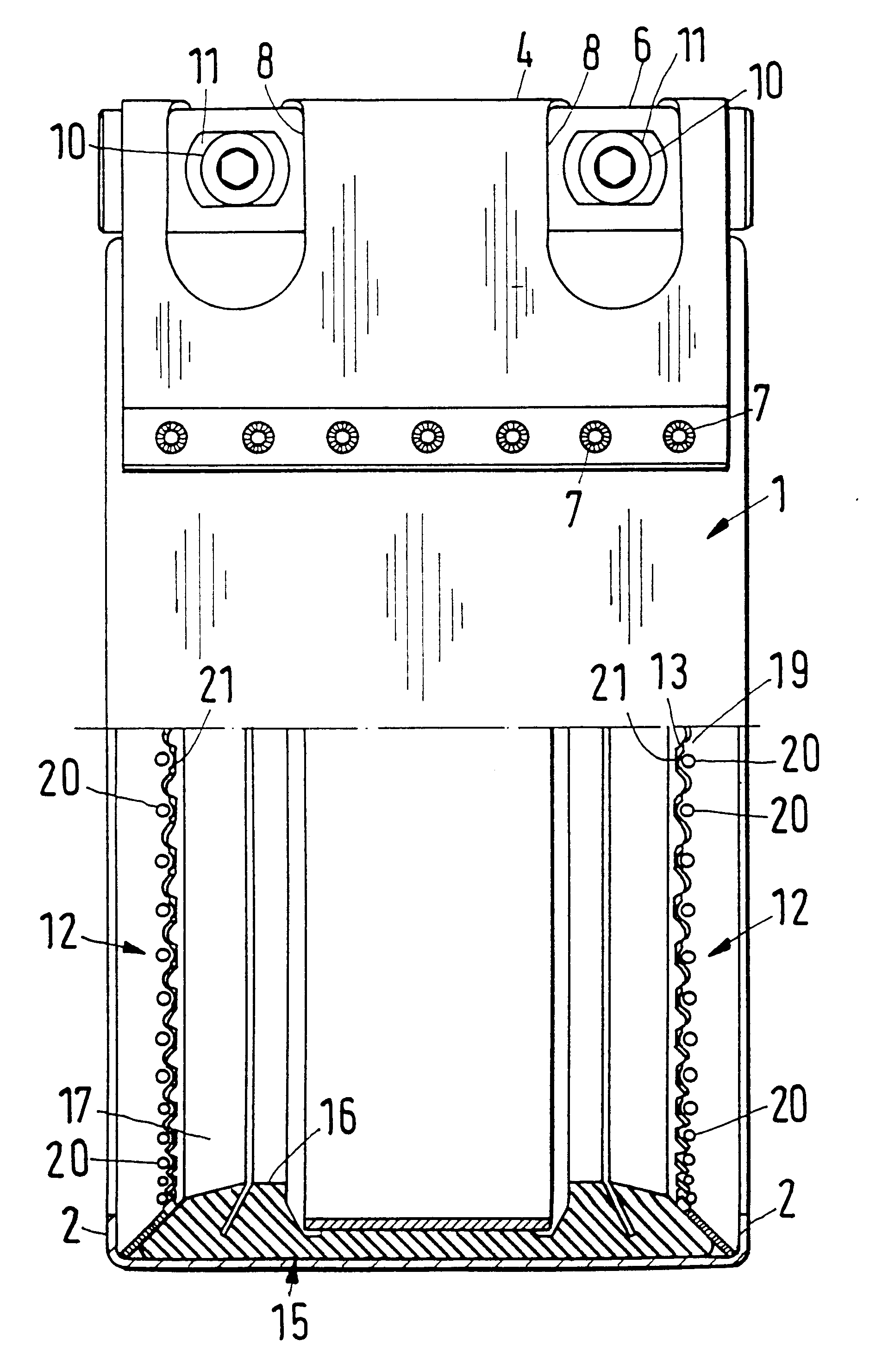
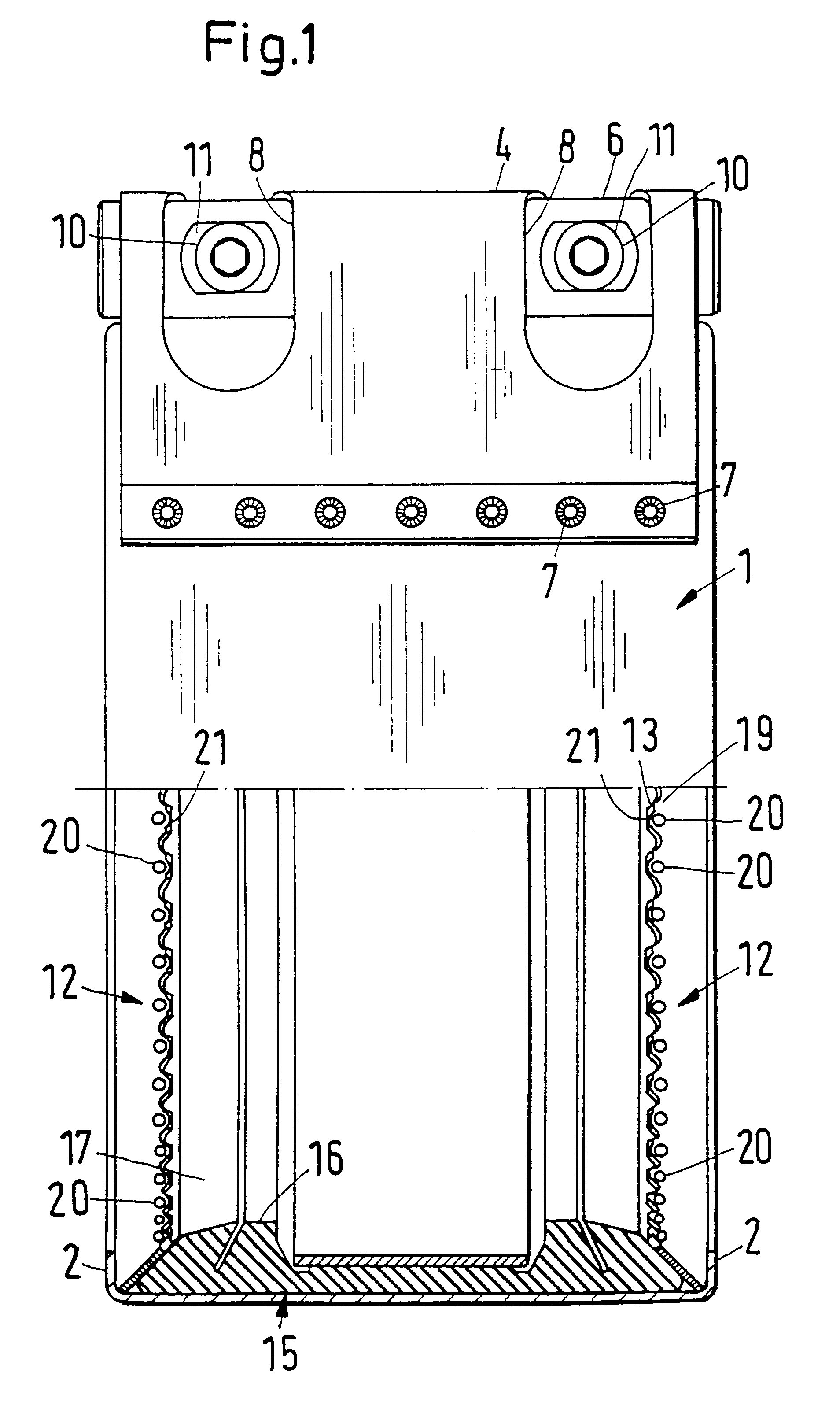
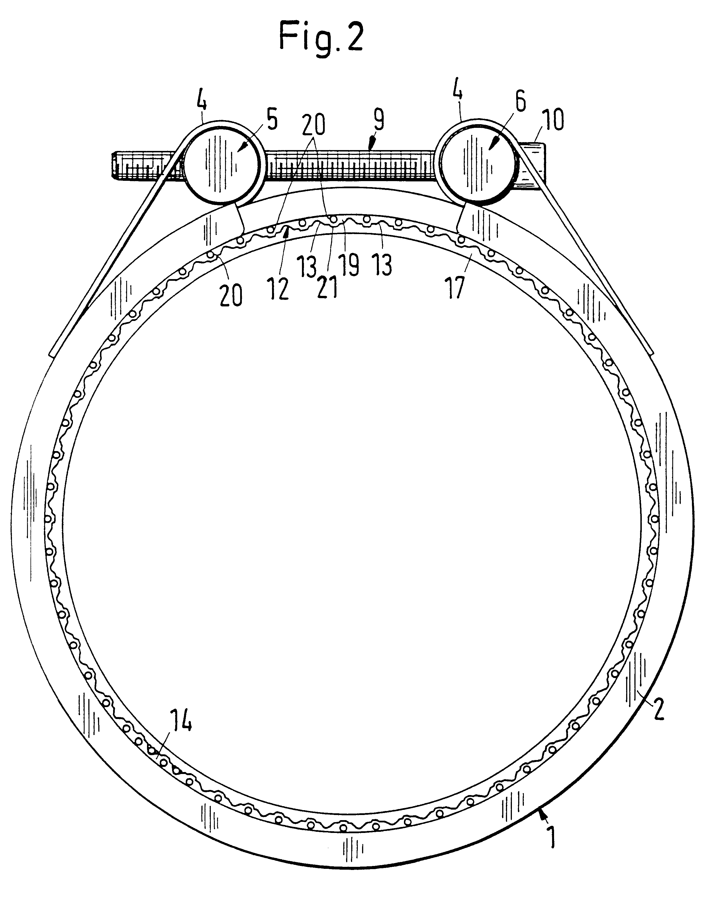
Referring now to FIGS. 1-7, a pipe coupling according to the present invention is illustrated. The pipe coupling includes an outer sheet steel casing 1 that is bent into less than a complete ring (see FIG. 2). Radially bent in front faces 2 are provided at each axial end of casing 1. The inner diameter of each front face 2 is larger than the outer diameter of the pipes 3 to be connected by the pipe coupling (see FIG. 3). Casing 1 is split or open in the circumferential direction, thereby forming the incomplete ring. The free ends of casing 1 are bent radially outwardly and back, thereby forming a loop 4 at each free circumfrential end of the incomplete ring (see FIGS. 1 and 2). The free ends of casing 1 are attached, via buckle weldments 7, to the outer surface of casing 1 (see FIG. 1). A bolt 5 is inserted in each loop 4. Each loop 4 has a slot 8 that extends around a major portion of each bolt 5, 6 (see FIG. 1). Each bolt 5, 6 has a through bore that is located in an area correspo...


PUM


Abstract

A pipe coupling axially connects two pipes having a smooth outer surface. The pipe coupling includes a first split circular ring and a second split circular ring. The first and the second split circular rings are made from a metal strip. Each of the strips have a radially inner edge surrounding the ends of the pipes. A plurality of teeth are disposed at the radially inner edge of the strips. The teeth are disposed in the plane of the respective rings. A free end of the tooth penetrates into the pipe when the coupling is in the clamped position. The teeth extend at an angle relative to a longitudinal axis of the pipes. A side of each of the teeth facing toward the pipe inserted in the coupling have, adjacent to the free end of the tooth, at least one indentation. The indentation displaces the material of the tooth on the side of the tooth in the direction toward the free end of the tooth.

Description

1. Field of the InventionThe present invention relates to a clampable pipe coupling to axially connect two pipes having a smooth outer surface. The coupling includes split annular or ring-shaped elements that are made from a metal strip. The rings have edge that, in the clamped position, surrounds the pipe ends. The radially inner radial edge of the rings have teeth that extend in the plane of the ring. The free ends of the teeth penetrate into the pipe material when the pipe coupling is in the clamped position. The teeth penetrate into one pipe and extend at an angle relative to the longitudinal axis of the pipe. The teeth also extend at an angle relative to the teeth that engage in the other pipe.2. Discussion of the Related ArtsConventional pipe couplings such as, for example, those described in German Reference No. DE 25 55 179B2, have teeth (which are also referred to as "claws") that are configured like pointed sawteeth. Circumferentially neighboring edges of the sawteeth are ...

Claims


Application Information

Patent Timeline
IPC IPC(8): F16L17/04F16L17/00F16L21/06
CPCF16L17/04F16L21/005F16L21/08Y10S285/906F16L33/02
Inventor SCHREITER, REINER
Owner NORMA GERMANY GMBH
Why Eureka
Try Eureka